78 | SAMLEX AMErICA INC.
SAMLEX AMErICA INC. | 79
6.3 oPerAtionAL inForMAtion through LeDS AnD buZZer
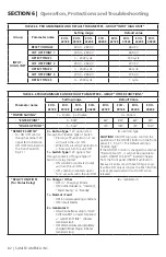
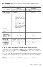
Table 6.1 shows the operational states of the unit indicated by the following LEDs on the
front panel of the unit and buzzer:
o
green LeD marked “on” (12, Fig 2.1)
o
red LeD marked “Fault” (13, Fig 2.1)
Optional remote Control Model EVO-rC (see Appendix A) will be required for more detailed
messaging that is available through its LCD display and LEDs. This remote will also be required
for programming of various parameters to suit specific requirements.
tAbLe 6.1 LeD AnD buZZer inDiCAtionS
Status
green LeD
marked “on”
(12, Fig 2.1)
red LeD
marked
“Fault” (13, Fig
2.1)
buzzer
Seen during Power-On
Sequence
Indicates completion of
Power-On Sequence after
Power ON/Off button is
pressed for 2 sec
flash 3 times
Off
Off
Seen during Power-Off
Sequence
Indicates completion of
Power-Off Sequence after
Power ON/Off button is
pressed for 5 sec
On
On
Off
Normal charging
flash 1 time per sec Off
Off
Equalization charging
flash 2 times per
sec
Off
Off
Inverting (Discharging)
On
Off
beep per 3 second
(Default Off)
Low battery alarm
On
flash 1 per sec
beep per 1 second
Power saving
flash 1 time per
3 sec
Off
Off
Standby
(See CAUTION! at page 85)
Off
Off
Off
fault
Off
On
On
SECTIOn 6 |
Operation, Protections and Troubleshooting


