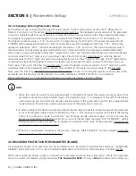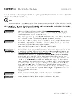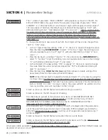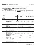
18 | SAMLEX AMERICA INC.
APPENDIX A
SECTION 3 |
Operation
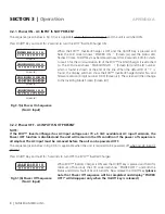
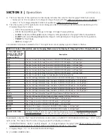
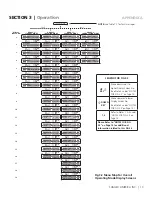
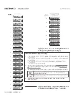
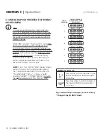
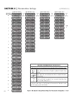
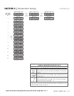
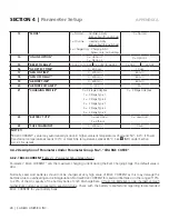
Fig 3.6 Menu Map for Display Screens during
"Charger Stop by BMS" Mode
DISPLAY
SCREEN NO.
DISPLAY SCREENS IN
CHARGER ONLY MODE
(NO AC INPUT)
1
I N V S T O P B Y B M S
B A T T E R Y 1 2 . 0 0 0 V
ò ñ
2
I N V S T O P B Y B M S
B A T T E R Y
0 . 0 0 V
ò ñ
3
I N V S T O P B Y B M S
G R I D
0 . 0 0 V
ò ñ
4
I N V S T O P B Y B M S
G E N
0 . 0 0 V
ò ñ
5
I N V S T O P B Y B M S
Y Y Y Y / MM / D D H H : M M
ò ñ
6
I N V S T O P B Y B M S
I D =
1
R C = X X X
1
ò ñ
7
I N V S T O P B Y B M S
E V O - X X X X
1
V X . X X
1
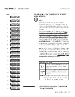
3.10 MENU MAP FOR “INVERTER STOP BY BMS”
MODE SCREENS
i
INFO
For background information, refer to Section
4.4.2.22.2 regarding “Stop Inverting” control by
Lithium Ion Battery Management System (BMS)
for on/off control of inverting operation of EVO
Inverter Charger
When BMS activates “Stop Inverting” signal
(The
Drain-Source terminals of the BMS will close
and short Pins 1/2/3/4 and 5/6/7/8 of RJ-45 Jack
marked “Battery Temp Sensor” on the front panel
of EVO)
, EVO will stop inverting
(Internally, EVO
will be in Standby Mode)
. 7 scrollable display
screens will be available to show the status of
various operating parameters as shown in the
Menu Map at Fig 3.6 on the right:
NOTE:
The 7 “INV STOP BY BMS” display screens
shown in Fig 3.6 on the right are the same as
the 7 display screens shown for Menu Map for
“Standby Mode” (Fig 3.2 – Column 2 under
heading “GROUP 1: STANDBY MODE”) but with
the 1
st
line replaced with “INV STOP BY BMS”
LEGEND FOR FIG 3.6
UP
ò
KEY
Press Up Key to scroll the screen in the
downward direction towards higher
Screen Nos
ñ
DOWN
KEY
Press Down Key to scroll the screen in
the upward direction towards lower
Screen Nos
UP
KEY
UP
KEY
UP
KEY
UP
KEY
UP
KEY
UP
KEY
DOWN
KEY
DOWN
KEY
DOWN
KEY
DOWN
KEY
DOWN
KEY
DOWN
KEY

