SAMLEX AMERICA INC. | 47
APPENDIX A
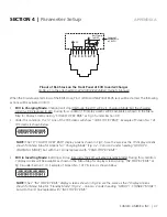
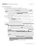
1 2 3 4 5 6 7 8
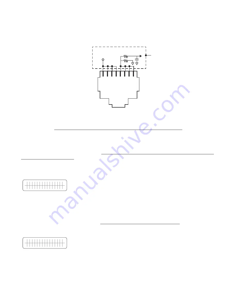
+5V
Internal
Schematic
of EVO
TM
Batt Temp
to DSP
1K
5.1K
Pinout of RJ-45 Jack on the Front Panel of EVO Inverter/Charger
(6, Fig 2.1 in the attached EVO-2212/3012/2224/4024 Owner's Manual)
When the Drain-Source terminals of the BMS close, Pins 1/2/3/4 and 5/6/7/8 of RJ-45 Jack will be shorted. The following
actions will be activated in EVO:
• EVO in Charging Mode:
Charging will stop
(Internally, the EVO will be in Charging Mode, but the charging
current will be reduced to 0A)
. During this condition, 19 display screens will be available as shown in the Menu
Map for Display Screens during “CHGR STOP BY BMS” at Fig 3.5 under Section 3.9.
• Under this condition, the 1st Line of the 19 Screens will show “CHR STOP BY BMS”.
Example of Screen No. 1 of
19 Screens is shown below:
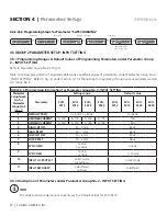
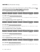
C H G R S T O P B Y B M S
O U T P U T
1 2 0 . 0 0 V
NOTE:
The 19 “CHGR STOP BY BMS” display screens shown in Fig 3.5 are the same as the 19 display screens
shown for Menu Map for screens for “Charging Mode” (Fig 3.2 – Column 3 under heading “GROUP 3:
CHARGING MODE”) but with the 1st line replaced with “CHGR STOP BY BMS”
• EVO in Inverting Mode:
Inverting will stop
(Internally, the EVO will enter Standby Mode)
. During this condition,
7 display screens will be available as shown in the Menu Map for display screens during “INV STOP BY BMS” at
Fig 3.6 under Section 3.10. Example of Screen No. 1 of 7 Screens is shown below:
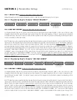
I N V S T O P B Y B M S
B A T T E R Y 1 2 . 0 0 0 V
NOTE:
The 7 “INV STOP BY BMS” display screens shown in Fig 3.6 are the same as the 7 display screens
shown for Menu Map for “Standby Mode” (Fig 3.2 – Column 2 under heading “GROUP 1: STANDBY MODE”)
but with the 1st line replaced with “INV STOP BY BMS”
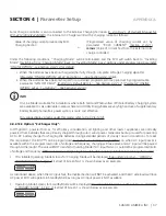
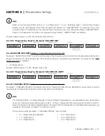
SECTION 4 |
Parameter Setup

