10 | SAMLEX AMERICA INC.
windings cool down to temperature ≤ 75°C ± 5°C / 167°f ± 9°f, the Switch will close, shut
down circuit will be de-activated and the Power Supply Section will be reset automati-
cally. During the time the Power Supply Section is shut down due to over temperature,
the backup battery will supply the load and will start discharging. When the Power
Supply Section cools down and resets, it will once again start supplying the load and
re-charge the battery.
oVeR VoLtAGe PRotection
over voltage protection is provided through the internal PWM controller
!
WARninGS!
PLeASe ReAD “Section 1 - SAFetY inStRUctionS” FoR SAFe inStALLAtion.
note:
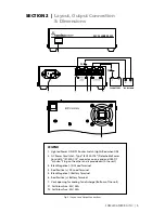
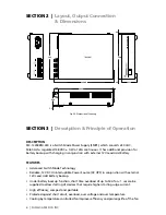
Please refer to fig 2.1, page 5 - Layout & output Connections
LocAtion, MoUntinG AnD SAFetY
The unit is required to be installed in a safe, well-ventilated and dry location. Please see
details given under Section 1 "Safety Instructions". The unit can be mounted horizon-
tally or vertically. When mounting vertically, please ensure that the output Terminals
are pointing up or down.
Ac inPUt connection
A detachable power cord has been supplied. Connect the power cord to the AC Power
cord Inlet (2). Plug the power cord to the AC outlet. Please ensure that the voltage of
AC input power at the outlet is 230 VAC, 50/60 Hz.
Dc oUtPUt connectionS
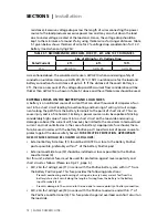
The Load Terminals (3,4) and the Battery Terminals (5,6) have 5mm / 0.2” diameter
tubular hole with set screw (#10, 24 TPI, 5/16” long).
for ensuring firm connection under the set screw, 4 pieces of Pin Type of Terminal Lugs
“PTNB10-12” have been provided for crimping to the bare ends of stranded wires for the
load and battery connections. The terminal can accept wire of up to 10 mm
2
/ AWG #8.
After crimping the Terminal Lugs, use insulating heat shrink tubing or tape to insulate
the bare cylindrical portion of the lug.
SeCtIOn 4 |
Protections
SeCtIOn 5 |
Installation


