12 | SAMLEX AMERICA INC.
SeCtIOn 5 |
Installation
resistance). Excessive voltage drop across the length of wires connecting the power
source to the load produces excessive power loss and may also shut down the load
due to under voltage created at the load end. Hence, the voltage drop should be
kept to the minimum at around 2% by using thicker wires for longer distances. Table
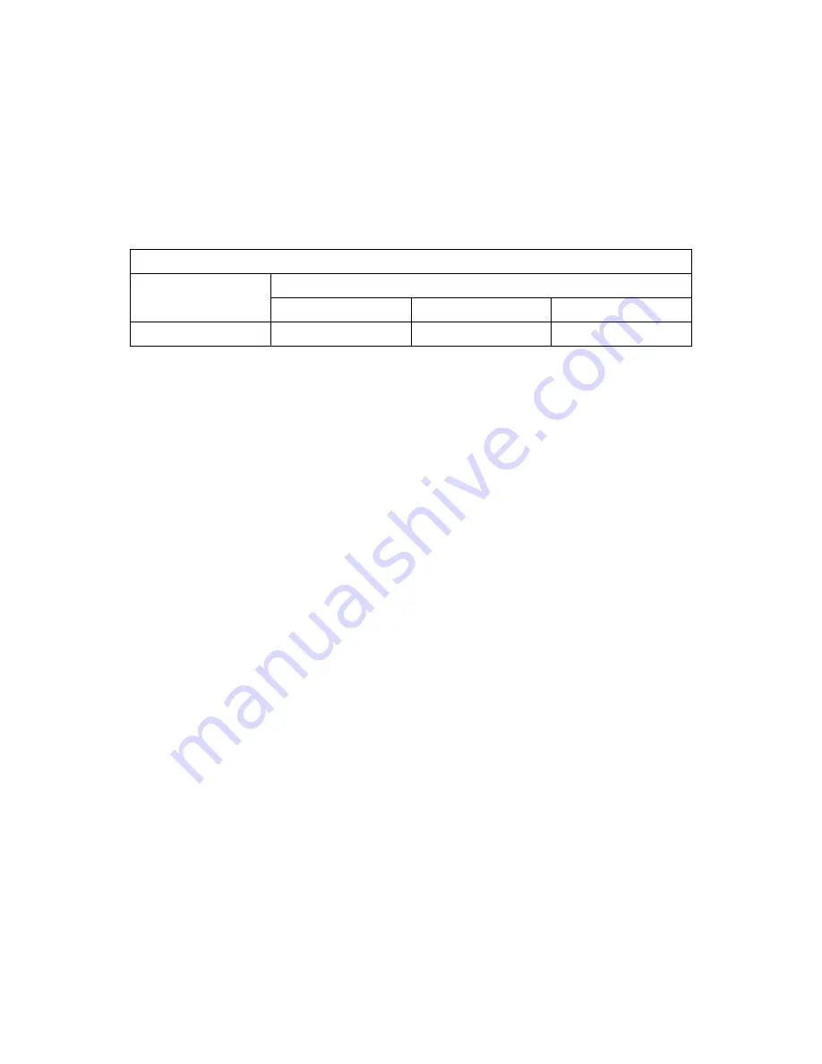
5.1 given below shows thickness of wire for 2% voltage drop consideration for 12 V
battery / load when carrying 25A:
tABLe 5.1: RecoMMenDeD WiRe SiZeS FoR 3 Ft., 6Ft. AnD 10 Ft. DiStAnceS
Rated current
Size of Wiring for 2% Voltage Drop
3 ft.
6 ft.
10 ft.
25A
AWG #10
AWG #8
AWG #6
As mentioned above, the calculated wire size is AWG #10 when considering safety of
conductor insulation. Hence, use AWG #10, 90°C / 194°f insulation wire for the load and
battery connections for a distance of up to 3 ft. If the distance of the Load / Battery is >
3 ft., the size on account of 2% voltage drop and 25A current flow consideration will be
thicker than AWG #10 as shown in Table 5.1 above and these thicker sizes should be used.
eXteRnAL FUSeS on tHe BAtteRY AnD LoAD SiDeS
A battery is an unlimited source of current that can drive thousands of Amperes of cur-
rent into a short circuit leading to overheating and burning of wiring / circuit compo-
nents along the path from the battery terminals to the point of short circuit. This can
cause injury and is a fire hazard. Similarly, a power source is also be capable of driving
considerably high value of current into a short circuit on the load side and causing
damage as above (the current will, however, be limited to the maximum rated overload
current and not unlimited as in the case of a battery). Appropriate fuse should, there-
fore, be used in series with the battery Positive post / Load terminal of power source to
protect against the above safety hazard. FoR eFFectiVe PRotection, APPRoPRiAte
SiZeS oF FUSeS SHoULD Be LocAteD AS FoLLoWS:
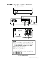
• External Battery Side Fuse (F1) should be LOCATED as close to the battery Positive
post as possible, preferably within 7” of the battery Positive post
• External Load Side Fuse (F2) should be installed as close as possible to the Positive
Load Terminal (4)
for this unit, external fuses must be used for protection against reverse polarity and
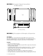
short circuit as follows (Please see fig 2.1, page 5.)
• 32V, 25A fast acting Fuse (F1) in series with the Positive battery wire within 7” from
the battery Positive post. This fuse provides the following protections:
-
Prevents overheating and burning of wiring due to very heavy current fed from the
battery into a short circuit along the length of wiring from the battery to the Battery
Input Terminals (5, 6).
-
Prevents damage to the unit and to the load due to reverse polarity of battery connection
• 32V, 25A fast acting Fuse (F2) in series with the Positive load wire and within 7” of
the Positive Load Terminal (4). This fuse protects against overload and short circuit on
the load side.


