background image

 18


3.3


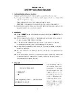
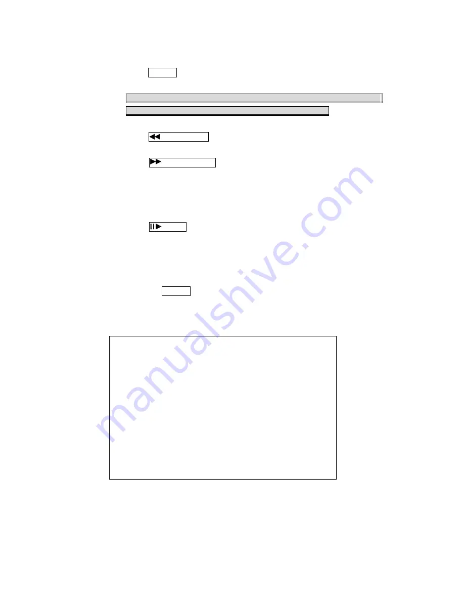
Several ways to perform playback: 

3.3.1


Press 

PLAY button to play video forward. 

3.3.2


"PLAY" sign will be indicated in top left corner on the screen. 

"MUX or QUAD" sign will be indicated in top right corner on the 
screen, it means the recording mode you selected.
 

3.3.3


When playback reaches the vary end of record and "END"will appear. 

Press 

Rew Search button to play video reverse at 16 times speed fast 

rewind mode. 

3.3.4


Press 

F.Fwd Search button to play video forward at high speed. Press 

the button again speed will be change circulative from ×4, ×8, to the 
highest ×16. 

3.3.5


"REW" or "FF* 4 / 8 / 16" sign will be indicated in top left corner on the 

screen. 

3.3.6


Press 

Pause button to pause (field by field) for forward. This function 

can be used in full screen and quad mode. 
(If you choose QUAD in recording mode than it can't playback in full 
single channel screen).
 

3.3.7


"PAUSE" sign will be indicated in top left corner on the screen. 

Press the 

STOP button to leave playback mode and resume to Live Mode. 


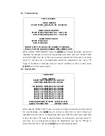
When overwrite mode is enabled with 2 hard drives, drive which is overwriting will 
cause recording time being divided to 2 periods as picture below: 

TIME  SEARCH 


HDD1: MASTER


 START TIME: 2005/MAY/04  08:00:00 


HARD DRIVE: MASTER 

START TIME

2005/MAY/05  08:12:03 

END TIME

2005/MAY/05  10:10:55 


HARD DRIVE: SLAVE 

START TIME

2005/MAY/03  08:12:03 

END TIME

2005/MAY/04  10:10:55 


[RIGHT/LEFT] TO MOVE [UP/DOWN] TO CHANGE 

[PLAY] TO PLAY [QUAD] CHANGE HDD [MENU] EXIT 

There will be 2 periods of time as RECORD SEGMENT 1 and RECORD SEGMENT 2 in 
master drive which means the oldest data and  newest  data  both  existing  on  the 
same hard drive. Above rules will also apply to slave hard drive. 


Summary of Contents for DR-S0426

Page 1: ...DR S0426 DRE S0426P 4 Channel Stand alone Digital Video Recorder ...

Page 2: ...INTERFERENCE CAUSING EQUIPMENT REGULATIONS WARNINGS CAUTIONS COPYRIGHT WARINGS TO REDUCE THE RISK OF FIRE OR ELECTRIC SHOCK DO NOT EXPOSE THIS PRODUCT TO RAIN OR MISTURE DO NOT INSERT ANY METALLIC OBJECT THROUGH VENTILATION GRILLS CAUTION Explanation of Graphical Symbols The lightning flash with arrowhead symbol within an equilateral triangle is intended to alert the user to the presence of insinu...

Page 3: ... SETUP 11 6 SCHDULED RECORD 12 7 EVENT LIST 12 8 HDD MANAGEMENT 13 9 LOAD DEFAULT 15 10 EXIT 15 CHARPTER 4 OPERATION PROCEDURES 16 1 GETTING STARTED WITH YOUR MACHINE 16 2 RECORDING 16 3 PLAYBACK 16 4 HARD DISK AND CF CARD RECOMMEND 19 5 VCR 19 6 ALARM CONTROL 19 7 EXTERNAL ALARM CONNECTOR 20 8 VGA OUTPUT 21 9 RS 485 CONTROL PROTOCOL 22 CHAPTER 5 SPECIFICATIONS 23 CHAPTER 6 RECORDING TIME LENGTH 2...

Page 4: ... ALARM SETUP BUZZER BUZZER DWELL 5SEC VIDEO LOSS ALARM ON MOTION ALARM OFF EXTERNAL ALARM ON RELAY VIDEO LOSS ALARM ON MOTION ALARM ON EXTERNAL ALARM ON EXTERNAL SENOR SETUP ALARM DISPLAY MODE OFF EXIT SCHEDULE SETUP 0 3 6 9 12 15 18 21 24 0 3 6 9 12 15 18 21 24 EVENTLIST HARDDRIVER MASTER STARTTIME 2005 MAY 1612 07 00 ENDTIME 2005 MAY 1612 07 30 01RECORD 2005 MAY 1612 07 00 02MOTCH12005 MAY 1612 ...

Page 5: ...manually or gets activated automatically when alarm is triggered z Motion detection function available user can easily adjust sensitive area of motion detection z Playback record can be searched by time or by event list z Play back mode could not be easier then ever for you to review the video that gets recorded on reverse x16 and fast forwarding 4 8 and 16 z Play back mode with pause field by fie...

Page 6: ...trols FULL SCREEN display from camera 1 2 A password can be setup by the view control button for number 1 7 2 1 This View button controls FULL SCREEN display from camera 2 2 A password can be setup by the view control button for number 2 8 3 1 This View button controls FULL SCREEN display from camera 3 2 A password can be setup by the view control button for number 3 9 4 1 This View button control...

Page 7: ...adjust position of date time display which appears on OSD 18 1 Move the cursor downward or increase the number 2 When it s not under recording mode you can use the button to adjust position of date time display which appears on OSD 19 MENU Press MENU to go into or exit menu 20 ENTER 21 ENTER 1 Press ENTER button to choose or confirm in MENU system 2 You can use ENTER key to indicates H D D status ...

Page 8: ... unit 28 CAMERA OUT Camera 1 4 video output with BNC connector 29 CAMERA IN Camera 1 4 video input with BNC connector 30 MONITOR OUT Composite video output with 2 BNC connectors 31 VGA SETUP DIP Setting Resolution Frequency Option 32 VGA D SUB OUT Connect to CRT or LCD monitor Option 33 Audio IN OUT Audio input output RCA connectors Option 34 ALARM IN Relay 8 Pin Alarm input and Relay output conne...

Page 9: ...MODE and AUDIO RECORDING STATUS While MENU mode without press any key would go back to live viewing mode after 2 minutes And during live viewing for 5 seconds would go back to recording mode automatically if full time or alarm record set before 1 MAIN SETUP MENU Press the MENU button to go into the main menu Use the or button to select items Press the or button to confirm the selection Press MENU ...

Page 10: ...tton to move or button to set up date time by MENU key back to menu 3 TIME DISPLAY MODE Use W or X button to change YY MM DD MM DD YY or DD MM YY 4 TIME DISPLAY ON OFF Use W or X button to change ON or OFF 5 LANGUAGE SELECT ENGLISH Use W or X button to change language 6 KEY LOCK ON OFF Use W or X button to change ON or OFF 7 MENU SETUP PROTECT ON OFF Use W or X button to change ON or OFF 8 CHANGE ...

Page 11: ...amera From 0 off to 5 MAX 4 MOTION AREA SETUP Use or button to enter motion area setup here provide 2 areas for setting PLAY to change the position or area mode to moving position or change area size CH1 for default minimum size CH2 for default size CH3 for default maximum QUAD for help information on screen MENU back to pervious menu 5 BRIGHTNESS 1 2 3 4 STANDARD 6 7 8 9 10 Use or button to adjus...

Page 12: ...7 10 15 30 you can choose NTSC default 30P PAL at 25P 3 ALARM RECORD DWELL 1 30SEC Use or button to set the dwell time for alarm recording when external alarm or motion detection is triggered There are a total of 30 speeds you can choose from 1 to 30 When external alarm is triggered and within the dwell period the screen will be switched into quad mode The corresponding camera will be marked ID EX...

Page 13: ...r button to select video loss alarm function on or off 3 MOTION ALARM ON OFF Use or button to switch function on or off when motion occur 4 EXTERNAL ALARM ON OFF Use or button to switch function on or off when external alarm occurs RELAY 1 VIDEO LOSS ALARM ON OFF Use or button to switch video loss alarm function form relay box 2 MOTION ALARM ON OFF Use or button to switch motion alarm function for...

Page 14: ... button to select hours Press or button to select the O X A Fully No Alarm Record QUICK KEY Play Key to switch between O X A Fully No Alarm Record in all hours 7 EVENT LIST Press or key on EVENT LIST or to enter Use the or button to select items Press the or button to confirm the selection Press MENU back to SETUP MENU Use or key to select event which needs to be played location of symbol will mov...

Page 15: ...est partition on HDD will automatically be reused and the oldest images will be overwritten the current images When overwrite mode is disabled the HDD Full Warning percentage selection will be appeared and need to be configured 2 HDD FULL WARNING 10 5 10 15 20 Use or button to select one of the four settings 5 10 15 20 The default is 10 The buzzer will turn on when free space left in the HDD go be...

Page 16: ...o page 2 SYSTEM SETUP CHANGE PASSWORD 6 SLAVE HDD CAPACITY N A The slave HDD capacity sign will be indicated on the screen it can t be revised HDD N A is with no HDD 7 SLAVE HDD LEFT RATIO N A The slave HDD left ratio sign will be indicated on the screen it can t be revised HDD N A is with no HDD 8 SLAVE HDD FORMAT Same with MASTER HDD FORMAT ...

Page 17: ...STEM SETUP ON OFF Use W or X button to ON for restore to default setting or OFF 3 CAMERA SETUP ON OFF Use W or X button to ON for restore to default setting or OFF 4 RECORD SETUP ON OFF Use W or X button to ON for restore to default setting or OFF 5 ALARM SETUP ON OFF Use W or X button to ON for restore to default setting or OFF 6 CONFIRM AND EXIT After setting above items and pressW or X button b...

Page 18: ...g 2 2 On information bar the MUX or QUAD sign will be indicated on the screen it means you select MUX or QUAD recording 2 3 15P sign will be indicated in top right corner on the screen it mean the recording speed you selected 15P means 15 fields per second 2 4 O sign will be indicated in center corner on the screen it means the marked channel is recorded 2 5 For more information on Setting up Reco...

Page 19: ...key to start playing back 3 2 Event List EVENT LIST HDD1 MASTER START TIME 2005 MAY 16 12 07 00 END TIME 2005 MAY 16 12 07 30 01 RECORD 2005 MAY 16 12 07 00 02 MOT CH1 2005 MAY 16 12 06 00 03 MOT CH2 2005 MAY 16 12 05 00 04 MOT CH3 2005 MAY 16 12 04 00 05 ALM CH1 2005 MAY 16 12 03 00 06 ALM CH2 2005 MAY 16 12 02 00 07 ALM CH3 2005 MAY 16 12 01 00 PRESS UP DOWN TO MOVE PLAY TO PLAY QUAD TO CHANG HD...

Page 20: ... be used in full screen and quad mode If you choose QUAD in recording mode than it can t playback in full single channel screen 3 3 7 PAUSE sign will be indicated in top left corner on the screen Press the STOP button to leave playback mode and resume to Live Mode When overwrite mode is enabled with 2 hard drives drive which is overwriting will cause recording time being divided to 2 periods as pi...

Page 21: ...rpm We DO NOT suggest Samsung Western Digital Maxtor DiamondMax 10 series hard drive base on technical examination 5 VCR 1 VCR Backup The DVR Provides composite signal output for back up use You can keep the Image data and simply just connected BNC connector at the Back Panel of with MONITOR OUT Connector Press VCR REC button after decided what recording data need to keep during Play Back Mode 6 A...

Page 22: ...e the external alarm a Texts ALM will be displayed on OSD corresponding channel b Relay action c Recording speed will be switch from normal mode to alarm mode refer to chapter 4 about recording setting d If setting A has been set in schedule recording will only perform recording when alarm is triggered during schedule A period Terminal connector Pin 1 4 ALARM1 ALARM4 Camera alarm input GND GND N C...

Page 23: ... DIP2 640 480 0 0 800 600 0 1 1024 768 1 0 1280 1024 1 1 Frequency DIP3 DIP4 56Hz 0 0 60Hz 0 1 70Hz 1 0 75Hz 1 1 DIP1 DIP2 DIP3 DIP4 Resolution Frequency Monitor 0 0 0 0 0 0 0 1 60 0 0 1 0 72 0 0 1 1 640 480 75 15 inch or below 0 1 0 0 56 0 1 0 1 60 0 1 1 0 72 0 1 1 1 800 600 75 15 inch or below 1 0 0 0 1 0 0 1 60 1 0 1 0 70 1 0 1 1 1024 768 75 15 17 inch 1 1 0 0 1 1 0 1 1 1 1 0 1 1 1 1 1280 1024 ...

Page 24: ...R ID number range 5 21 2 Byte Refer to below table Command for each key string 3 Byte First byte plus Second byte Command for confirm checksum Part Label Command 5 REC 0x21 6 CH1 0x11 7 CH2 0x12 8 CH3 0x13 9 CH4 0x14 10 CHALL 0x15 11 COPY NONE 12 RFAST 0x3A 13 STOP 0x51 14 PAUSE 0x3D 15 FFAST 0x3E 16 PLAY 0x52 17 UPRT 0x31 18 DNLT 0x32 19 MENU 0x20 20 LEFT 0x33 21 SELECT ENTER 0x35 ...

Page 25: ...Compress Rate Low 8K bytes field Medium 10K bytes field High 15K bytes field Best 20K bytes field Recording Mode Manual Alarm Schedule Playback Speed Fast Forward 4 8 16 Fast Reverse 16 Frame by Frame Forward Playback On Screen Display Setup Time Date Setup Menu Alarm Input 4 Relay Output NO or NC Programmable Contact 1 Password Control One for HDD format Event List Max 63 records H D D Motion Det...

Page 26: ...1hr 214hr 285hr 426hr 870 hr medium 35 hr 70 hr 105 hr 148hr 213hr 266hr 350hr 532hr 1050hr Recording Quality low 50 hr 100 hr 150 hr 208hr 300hr 375hr 500hr 750hr 1500hr 80GB H D D Record Mode MUX PAL Field Sec 25 FS 12 FS 8 FS 6 FS 4 FS 3 FS 2 FS 1 FS maximum 35 hr 72 hr 110 hr 145 hr 218 hr 291 hr 437 hr 875 hr high 46 hr 95 hr 144 hr 190 hr 287 hr 383 hr 575 hr 1150 hr medium 67 hr 139 hr 209 ...

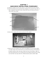
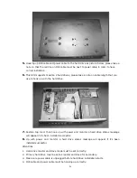
Page 27: ...from location shown below 3 Below picture indicates DVR which one without a H D D installed 4 Please refer to the instruction from hard drive manufactory for correct jumper setting on master slave mode of the hard drive mounting the hard drive over DVR base by facing IDE interface to DVR main board Match screw holes from bottom to bottom of hard drive and the DVR Turn over the DVR from top to bott...

Page 28: ...ard drive 7 Restore top cover then hook up with power and monitor a hard drive status message will appear if it s been installed successful 8 Up with power and monitor a hard drive status message will appear if it s been installed successful Attentions 1 Hard drive master and slave mode must be set correctly 2 Primary hard drive must be set as master and slave for secondary 3 Make sure power cable...

Page 29: ...27 a11633RM4F17 ...

Reviews: