background image

Please see the User’s Manual to check V-CHIP. 
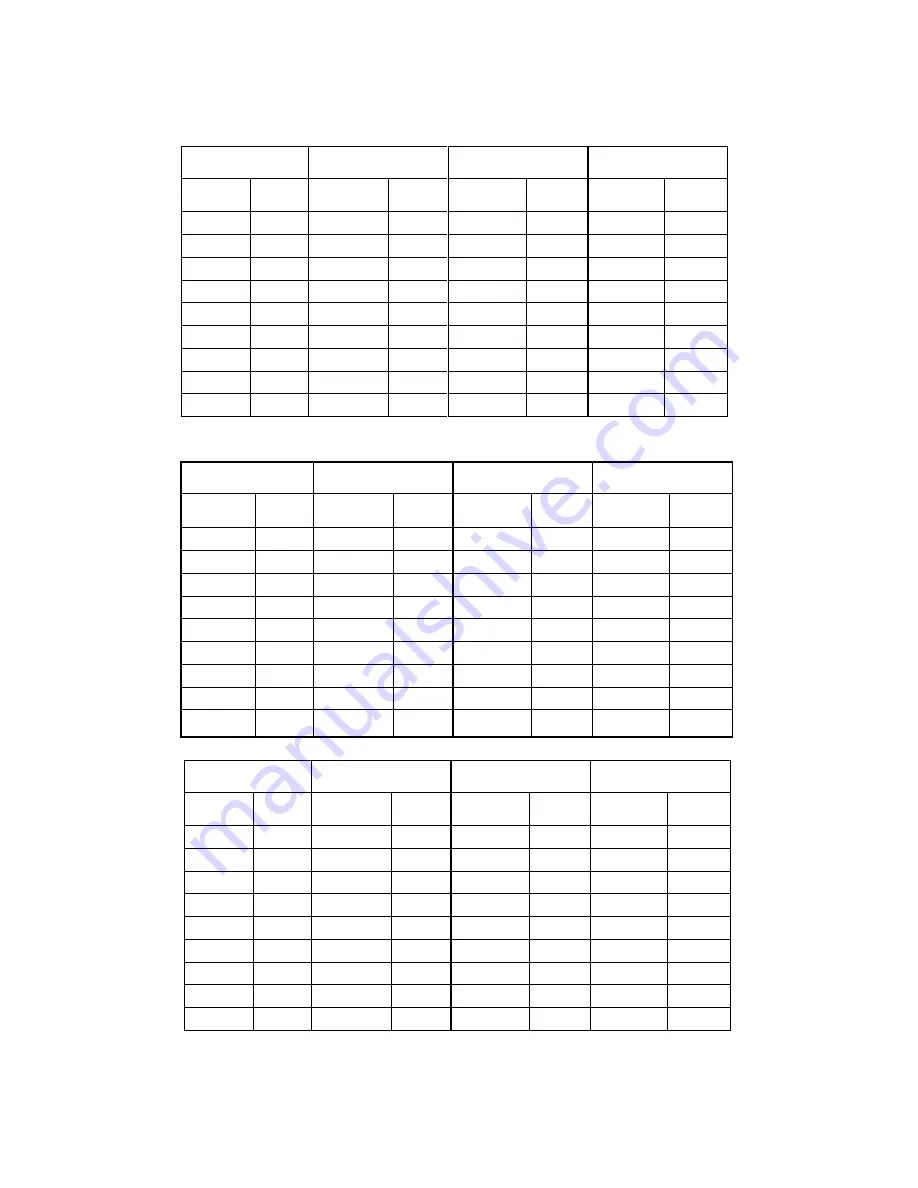
     

FAC 0

1


FAC 02 

FAC 02 

FAC 03 

Item Data 

Item  Data 

Item  Data Item  Data 

RC  

*

 80  HIGH5 

*

 0C 

HIGH6 

*

0E HPOS5

 *

 0E 

GC  

*

 80  VP50 

 *

 03 

VP60 

 *

03 PARA5

 *


1

BC 

 *

 80  VLIN5 

*

 0B 

VLIN6 

*

0A TRAP5

 *

 2C 

GD  

*

 40  VSC5 

 *

 09 

VSC6 

 *

09 HSIZE5

*

 2D 

BD  

*

 40  VBLK5  00  VBLK6  00 

CNRT5

 *

 0C 


VCEN5 

0E 

VCEN6 

2E 

CNRB5 

*

 0E 


   VEHT5 

03 


   HEHT5 

03 


FAC 03 

FAC 04 

FAC 05 

FAC 06 

Item Data 

Item  Data 

Item  Data 

Item  Data 

HPOS6

 *


1

2 CNTX  7F  BRTC  40  ST3  20 

PARA6

 *


1

6 CNTN  08  COLC  2C  SV3  20 

TRAP6

 *

 2B 

BRTX 

20 

COLP 

00 

SV4 

1

HSIZE6

*

 2C 

BRTN 

20 

SCOL 

07 

SVD 

1

CNRT6

 *

 0B 

COLX 

35 

SCNT 

0C 

ASSH 

07 

CNRB6 

*

 0D 

COLN 

00 

CNTC 

4C 

SHPN


1

VEHT6 03  TNTX  28  TNTCT  40  SHPN  2A 
HEHT6 03  TNTN  28  TNTCV  40   


FAC 07 

FAC 08 

FAC 09 

FAC 

1

Item Data 

Item  Data 

Item  Data Item  Data 

MOD

1

 60  RFAGC

 *

 25 

V0

1

 46 MODE4 

FF 

MOD2 B0  BRTS  00  V25 

6B  MODE5 3F 

MOD3 F0  OSD 

2

1

 V50  75  MODE6 

1

OPT 37 OSDF  53 V

1

00 7F MODE7 

57 

OPTM

1


6

1

 CCD 

OSD 

4A  VOLMAX 

32  MODE8 24 

OPTM2 C6  CCD 

OSDF 

65  CURTCEN

A5 

MODE9  FF 

HDCNT 00  TXCN 

1

F GATE 2A   


HSTOP FF  RGCN 

1

6 VOL-OUT

73   


23

Summary of Contents for SC-29FA15

Page 1: ...Procedure 21 5 Block Diagram 224 6 Schematic Diagram 25 7 PCB Layout 26 8 Exploded View Diagram 27 This manual is the latest at the time of printing and does not include the modification which may be...

Page 2: ...of uninsulated voltage within the products enclosure that may be of sufficient magnitude to constitute a risk of electric shock to the person The exclamation point within an equilateral triangle is i...

Page 3: ...nnel 8 Do not subject your television set to impact of any kind Be particularly careful not to damage the picture tube surface 9 Unplug this television set from the wall outlet before cleaning Do not...

Page 4: ...porting structure grounding of the lead in wire to an antenna discharge unit size of grounding conductors location of antenna discharge unit connection to grounding electrode and requirements for the...

Page 5: ...21 If you are unable to restorenormal operation by following the detailedprocedurein your operating instructions do not attempt any further adjustment Unplug the set and call your dealer or service te...

Page 6: ...oise Reduction Picture Display Display Type DV CRT FSQ Screen Format 4 3 Size Visual size vis cm 25 Deflection System CRT only Tube Technology CRT only Black Matrix Iron CRT Defl CRT Gun Stand Gun CRT...

Page 7: ...Cinch Audio Mono Out Cinch Dolby Surround Dig Audio Out Loudspeakers Control Busses Feature Slot ITV Smart Port Terr Antenna in 75 Ohms F type Guide IR Blaster Jack Connectors Front In Cinch CVBS St I...

Page 8: ...tion Tests Local Integration Various Perf Param Service Call Rate PIP POP Type Features Digital Reception Transmission Built in Data System Text Standard Tele text Features Nbr bckgrnd page Mem Size T...

Page 9: ...E04 SOFTWARE CODE 1 FOR IC001 PC 74 015020 50Q PLASTIC BAG 1 FOR CRT BD PACKING PC 74 060060 40F POLYBAG ANTISTATIC MAIN PCB 1 PC 75 326030 C00 SKD POLYFOAM 1 25 PC 76 002509 0AC CARTON BOX 0 084 PC 7...

Page 10: ...1001 PC 10 1N4148 ABX DIODE 1N4148 SWITCHING 3 L501 FOR TO P503 1 PC 11 A562TM 0BX TRANSISTOR 2SA562TM 0 1 Q507 PC 11 SC1815 YBX TRANSISTOR 2SC1815 Y NPN 3 Q502 Q504 Q506 PC 11 SC4544 0AX TRANSISTOR 2...

Page 11: ...KE 600 UH 1 L413 PC 37 SC2701 68V01 FBT BSC27 0168V 1 T402 PC 75 388320 CC0 POLYFOAM BOARD 0 05 FOR PMC PC 89 242080 JZ0 TRANSPARENT PACKING 6CMX41M 1 3 FOR PMC M 07 457FF5 NX7G ALPS FS TUNER TEDH9 24...

Page 12: ...1 2 PC 72 BT17A6 C039A OPERATION MANUAL 1 PC 74 010050 40C POLYBAG FOR POWER 10CMX50CM 1 PC 74 022032 6WEAD PLASTIC BAG 1 PC 74 130130 80HAA POLYBAG W SUFFOCATION WARNING 1 PC 75 444370 EC0 POLYFOAM...

Page 13: ...RES C F 22K OHM 1 6W 5 1 R091 PC 18 CB0470 JNX RES C F 47 OHM 1 6W 5 1 R089 PC 25 BCB221 M1X CAP ELEC 220 UF 16V 20 1 C081 PC 25 BCB470 M1X CAP ELEC 47 UF 16V 20 1 C080 PC 40 BT18S6 IRA1XG IR RECEIVE...

Page 14: ...DBX DIODE ZENER 6V2 1 2W 5 1 D207 PC 10 79C8V2 DBX DIODE ZENER 8V2 1 2W 5 1 D303 PC 10 GBY228 F0X DIODE GBY228 1 D411 PC 10 HS5V1B DBX DIODE 500MW 5 1HSB 1 D001 PC 11 2SA817 AAX TRANSISTOR 2SA817AY 1...

Page 15: ...2 R008 R007 PC 18 CB0394 JNX RES C F 390K OHM 1 6W 5 1 R939 PC 18 CB0470 JNX RES C F 47 OHM 1 6W 5 1 R024 PC 18 CB0471 JNX RES C F 470 OHM 1 6W 5 3 R238 R103 R036 PC 18 CB0472 JNX CARBON RES C F 4 7K...

Page 16: ...CAP ELEC 0 22UF 50V 10 1 C216 PC 25 MFB478 K1X CAP ELEC 50V 0 47UF 10 1 C246 PC 26 AIC221 KBX CAP CER 220 PF 500V 10 B 2 C433 C441 PC 26 AIC332 KBX CAP CER 3300 PF 500V 10 1 C402 PC 26 AIC391 KBX CAP...

Page 17: ...ER 10MM 1 J001 PC 41 WJ0105 B00 WIRE BARE JUMPER 10 5MM 4 J608 J607 J018 J214A PC 41 WJ0110 B00 WIRE BARE JUMPER 11MM 7 J024 J028 J228 J613 J042PC 41 WJ0115 B00 WIRE BARE JUMPER 11 5MM 3 J912 J939 J03...

Page 18: ...SB60 7109 1 DB801 PC 11 C144ES 0BX TRANSISTOR PDTC144ES NPN 2 Q804 Q803 PC 11 P08P06 0AX TRANSISTOR SPP08P06P 1 Q802 PC 11 SK3451 0CX TRANSISTOR 2SK3451 01MR 1 Q801 PC 13 000TL4 31T IC TL431ACLP 1 IC8...

Page 19: ...825A C807 PC 26 AMM221 JZX CAP CER 220PF 2KV 5 SL 2 C831 C852 PC 26 AMM331 JZX CAP CER 330 PF 2KV 5 SL 1 C834 PC 26 AMM561 KDX CAP CER 560 pF 2KV 10 D 1 C817 PC 26 APK102 ME4 CAP CER 1000PF 400VAC 20...

Page 20: ...2 FOR T801 PC 66 343730 0B0 HOLLOW RIVET 1 6MMX3 0MMX3 2M 6 FOR T803 1 9 7 10 12 18 PC 66 343730 0B0 HOLLOW RIVET 1 6MMX3 0MMX3 2M 7 FOR C801 1 2 FOR RT801 PC 66 382330 0B7 RIVET 2 0X3 7X3 5 8 FOR IC8...

Page 21: ...lance adjustment Mode Be used for White balance adjustment In Factory Mode press BUS OFF to enter and exit Default Value OK mode Be used for default value setting before TV leaves Factory In Factory M...

Page 22: ...t step 2 3 to make X 284 Y 299 Note M134 chassis can adjust white balance automatically In factory mode press I2C BUS to enter in The white balance in the other two colors temperature is Warm 296 296...

Page 23: ...HPOS6 12 CNTX 7F BRTC 40 ST3 20 PARA6 16 CNTN 08 COLC 2C SV3 20 TRAP6 2B BRTX 20 COLP 00 SV4 19 HSIZE6 2C BRTN 20 SCOL 07 SVD 19 CNRT6 0B COLX 35 SCNT 0C ASSH 07 CNRB6 0D COLN 00 CNTC 4C SHPN 10 VEHT...

Page 24: ...m Data Item Data Item Data RC C 80 RC W 80 D COL 32 S COL 32 GC C 80 GC W 80 D BRI 32 S BRI 32 BC C 80 BC W 80 D CON 5A S CON 32 GD C 40 GD W 40 D SHP 32 S SHP 32 BD C 40 BD W 40 YUVGC 03 YUVBC 03 FAC...

Page 25: ......

Page 26: ......

Page 27: ......

Reviews: