background image

Important Safety Instructions

1.  

Please read all instructions before operating the unit. 

2.  

Keep these instructions for future reference. 


3.  

Please heed all safety warnings. 

 
4.  

Follow manufacturers instructions.   

5. 

Do not use this unit near water or moisture. 

6.  

Clean only with a damp cloth.  

7. 

 Do not block any of the ventilation openings. Install in accordance with the manufacturers instructions. 

8.  

 Do not install near any heat sources such as radiators, heat registers, stoves, or other apparatus (includ-
ing amplifiers) that produce heat.  

 
9.  

 Do not defeat the safety purpose of the polarized or grounding-type plug. A polarized plug has two 
blades with one wider than the other. A grounding type plug has two blades and a third grounding 
prong. The wide blade or third prong is provided for your safety. When the provided plug does not fit 
your outlet, consult an electrician for replacement of the obsolete outlet.  

10.    Protect the power cord from being walked on and pinched particularly at plugs, convenience recep-

tacles and at  the point at which they exit from the unit.  

11.   Unplug this unit during lightning storms or when unused for long periods of time.  

12.    Refer all servicing to qualified personnel. Servicing is required when the unit has been damaged in 

any way, such as power supply cord or plug damage, or if liquid has been spilled or objects have fallen 
into the unit, the  unit has been exposed to rain or moisture, does not operate normally, or has been 
dropped.

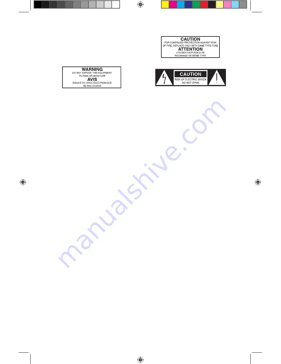
WARNING

: To reduce the risk of fire or electric shock, do not expose this unit to rain or moisture. 

The lightning flash with an arrowhead symbol within an equilateral triangle, is intended to alert the user to the 
presence of uninsulated "dangerous voltage" within the products enclosure that may be of sufficient magni-
tude to constitute a risk of electric shock to persons.  

The exclamation point within an equilateral triangle is intended to alert the user to the presence of important 
operating and maintenance (servicing) instructions in the literature accompanying the product.  

Caution:

 To reduce the hazard of electrical shock, do 

not remove cover or back. 

No user serviceable parts inside. Please refer all servic-
ing to qualified personnel. 

KM60100_ownman_v1.indd   2

11/21/05   10:38:36 PM

Summary of Contents for 100

Page 1: ... KM60100_ownman_v1 indd 1 11 21 05 10 38 34 PM ...

Page 2: ...point at which they exit from the unit 11 Unplug this unit during lightning storms or when unused for long periods of time 12 Refer all servicing to qualified personnel Servicing is required when the unit has been damaged in any way such as power supply cord or plug damage or if liquid has been spilled or objects have fallen into the unit the unit has been exposed to rain or moisture does not oper...

Page 3: ...516 364 3888 Table of Contents Introduction 2 Hartke KM60 and KM100 Keyboard Amplifier Features 3 Guided Tour Front Panel 4 Guided Tour Rear Panel 6 Setting Up and Using Your KM60 and KM100 7 Using the Footswitch Jack and Effects Loop 9 KM60 and KM100 Sample Settings 10 Specifications 13 KM60100_ownman_v1 indd 1 11 21 05 10 38 36 PM ...

Page 4: ...on makes them reli able performers from night to night and venue to venue Although these units are designed for easy operation we suggest you first take some time to go through these pages so you can fully understand how we ve implemented a number of unique features In these pages you ll find a detailed description of the many features of the KM60 and KM100 keyboard amplifiers as well as a guided ...

Page 5: ...a 10 inch custom designed Hartke Aluminum Cone Low Frequency Drive Unit and the KM100 emlpoys a 12 inch custom designed Hartke Aluminum Cone Low Frequency Drive Unit To capture and project the high frequencies of your keyboard rig the the KM60 utilizes a ceramic tweeter and the KM100 a 1 inch Throat Titanium Compression Driver A 7 band Graphic Equalizer is provided to shape the overall tone of the...

Page 6: ...vel of the Channel 4 input 7 Graphic Equalizer These sliders allow you to draw the tonal response of the system by adding 12 dB of boost or attenuation to seven different narrow band frequency areas 100 Hz 250 Hz 500 Hz 1 kHz 2 5 kHz 5 kHz and 10 kHz affecting the main output signal of the KM100 When a slider is at its center detented 0 position the selected frequency area is unaffected it is said...

Page 7: ...aker output is disconnected allowing you to use your KM60 or KM100 as a practice amplifier The level of the signal sent to the headphones is determined by the setting of the Output knob at the point where a connected speaker would clip the headphones will clip WARNING Because even the smallest KM Series amplifier is capable of generating extremely high headphone signal levels always start with the...

Page 8: ... to connect a microphone connect a low impedance mic to the Channel 1 XLR mic input located on the front panel 4 Set the main Volume control to 0 fully counterclockwise and set channel volume knobs to 5 the twelve o clock posi tion Then set the graphic equalizer sliders to the middle 0dB position 5 Press the front panel Power switch in order to turn on the amplifier WARNING Hartke amplifiers can d...

Page 9: ...ing Up and Using Your Hartke KM60 and KM100 Keyboard Amplifier 8 Your KM series amplifier features a AUX CD input which you can use with a portable CD player cassette mini disk or MP3 player to jam with pre recorded tracks or learn a riff from a favorite tune In fact you can plug any line level signal into the AUX input including the signal from a keyboard or drum machine Connect the CD player or ...

Page 10: ...impedance 100 ohm with an output level of approximately 30 to 20 dB You can also use the Direct Out jack to route signal to an external amplifier with a 10 dB input sensitivity KM60 or KM100 Stereo Set up You can use two KM60 s or KM100 s for stereo operation by simply connecting the left output of your keyboard to one KM60 or KM100 and the right output of your keyboard to the second KM60 or KM100...

Page 11: ...equency bands The seven band graphic equalizer provides seven sliders each corresponding to a single narrow frequency band 100 Hz 250 Hz 500 Hz 1 kHz 2 5 kHz 5 kHz and 10 kHz This allows you to draw the desired tonal response of your sys tem When a slider is in its center position 0 it is having no effect When it is moved above center towards 12 the particular frequency area is being boosted when ...

Page 12: ...ly to your Keyboard signal is very much dependent upon your par ticular instrument and personal taste and playing style However here are a few general sugges tions For that super deep reggae or techno bass sound boost low frequencies slightly while attenuating the highest ones leave mid range frequencies flat or slightly attenuated as shown in the illustration on the right To remove boxiness and m...

Page 13: ...n Left and Right RCA Headphone St TRS 1 4 phone Speaker Output 1 4 phone KM100 only Speaker System Impedance Ohms 4 Ohms Impedance Low Frequency Drivers KM100 12 Special Design Hartke Aluminum 4 ohm 100 watt Drive Unit KM60 10 Special Design Hartke Aluminum 4 ohm 60 watt Drive Unit High Frequency Driver KM100 1 Throat Compression Driver KM60 Ceramic Tweeter Weight KM100 74 8 lbs 34 kg KM60 50 lbs ...

Page 14: ...12 KM60 and KM100 Block Diagram KM60100_ownman_v1 indd 12 11 21 05 10 38 47 PM ...

Page 15: ...KM60100_ownman_v1 indd 13 11 21 05 10 38 48 PM ...

Page 16: ...Hartke Phone 1 800 372 6766 Fax 516 364 3888 www hartke com KM60100_ownman_v1 indd 14 11 21 05 10 38 48 PM ...

Reviews: