EB 2043 EN
21
Mounting and start-up
4
3
5
4
3
5
1
7
4
1
6
6
2
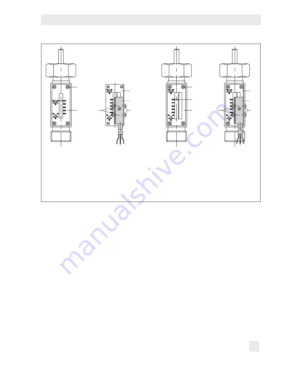
1 Screws
2 Dial plate
3 Switch
4 Dial plate
5 Screws
6 Nuts
7 Pointer
Fig. 5:
Mounting an electric signal transmitter
4. Align the switch (3) with the scale and
secure the switch to the dial plate by
slightly tightening the bolts (5) and nuts
(6).
Adjusting the signal transmitter
1. Reduce the limit value of the safety tem-
perature monitor by turning the key (10
in Fig. 2) until the pointer (7) of the travel
stem reaches the value '0' on the scale.
2. Connect the black and the blue wires of
the supply cable to a continuity tester or
a test lamp.
3. Move the switch (3) slightly until the test
lamp lights up. Then tighten the bolts (5).
4. For checking purposes, increase the limit
value. The test lamp should go out.
5. Reduce the limit value. The test lamp
should light up again when the value '0'
is indicated on the scale.


