background image

EB 8048 EN


 25

Shipment and on-site transport

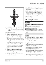
Fig. 7: 

Ball body version of Type 3249 with 

Type 3271 Actuator fitted with a lifting 

eyelet

Lifting the control valve

1. 

Carefully guide two slings through the 

yoke and attach them to the rigging 
equipment of the crane or forklift (see 

Fig. 5 and Fig. 6). Make sure that the ac

-

tuator stem and valve accessories are not 
damaged.
For actuator versions with lifting eyelet, 
attach an additional sling to the lifting 
eyelet of the actuator and to the rigging 
equipment of the crane or forklift (see 

Fig. 7).

2. 

Carefully lift the control valve. Check 

whether the lifting equipment and acces-
sories can bear the weight.

3. 

Move the control valve at an even pace 
to the site of installation.

4. 

Install the valve into the pipeline (see sec-

tion 5.3.2).

5.  After installation into the pipeline: de-

pending on the type of connection (e.g. 

welding joint, flanged joint etc.) check 

whether the valve in the pipeline holds.

6. 

Remove slings.

4.4 

Storing the valve

Risk of valve damage due to improper stor-

age.


Î

Observe the storage instructions.


Î

Avoid long storage times.


Î

Contact SAMSON in case of different 

storage conditions or long storage peri-
ods.

We recommend regularly checking the con

-

trol valve and the prevailing storage condi-
tions during long storage periods.

Storage instructions


Protect the control valve against external 
influences (e.g. impact).


Secure the valve in the stored position 
against slipping or tipping over.


Do not damage the corrosion protection 

(paint, surface coatings). Repair any 

damage immediately.


Protect the control valve against moisture 

and dirt. Store it at a relative humidity of 

NOTICE

!

NOTICE

!

Note

Summary of Contents for 3249

Page 1: ...dition December 2019 Type 3249 Aseptic Angle Valve In combination with an actuator e g a SAMSON Type 3271 or Type 3277 Pneumatic Actuator Ball body version Special version with packing Type 3249 Valve...

Page 2: ...s about these instructions contact SAMSON s After sales Service Department aftersalesservice samsongroup com The mounting and operating instructions for the devices are included in the scope of delive...

Page 3: ...18 4 Shipment and on site transport 22 4 1 Accepting the delivered goods 22 4 2 Removing the packaging from the valve 22 4 3 Transporting and lifting the valve 22 4 3 1 Transporting the valve 23 4 3 2...

Page 4: ...Replacing the diaphragm and plug 43 9 4 2 Replacing the packing 44 9 5 Ordering spare parts and operating supplies 44 10 Decommissioning 45 11 Disassembly 47 11 1 Removing the valve from the pipeline...

Page 5: ...intended purpose or for damage caused by external forces or any other external factors Refer to the technical data and nameplate for limits and fields of application as well as possible uses Reasonab...

Page 6: ...position of the control valve upon air supply or control signal failure depends on the actuator used see associated actuator documentation When the valve is combined with a SAMSON Type 3271 or Type 32...

Page 7: ...y with the requirements of the European Pressure Equipment Direc tive 2014 68 EU Valves with a CE marking have a declaration of conformity which in cludes information about the applied conformity asse...

Page 8: ...on the process medium valve components and pipelines may get very hot or cold and cause burn injuries Allow components and pipelines to cool down or heat up Wear protective clothing and safety gloves...

Page 9: ...ime release any stored energy in the actuator e g spring compression See associated actuator documentation Risk of personal injury due to preloaded springs Valves in combination with pneumatic actuato...

Page 10: ...Risk of valve damage due to contamination e g solid particles in the pipeline The plant operator is responsible for cleaning the pipelines in the plant Flush the pipelines before start up Risk of val...

Page 11: ...the valve material Unsuitable lubricants may cor rode and damage the surface Only use lubricants approved by SAMSON u AB 0100 Risk of valve damage due to the use of unsuitable lubricants The lubrican...

Page 12: ...ed actuator documentation 2 3 Material numbers The seat and plug of the valves have an item number written on them Specifying this item number you can contact us to find out which material is used Bod...

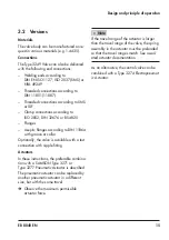
Page 13: ...t KV CV Characteristic equal percentage L linear 7 Seat plug seal ME metal PK soft PEEK seal PT soft PTFE seal 8 Serial number 9 Configuration ID 10 Compliance with food industry requirements 11 CE ma...

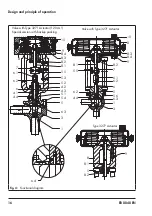
Page 14: ...moved by changing the signal pressure acting on the diaphragm of the actuator 8 4 The plug stem 6 is connected to the actua tor stem 8 1 by the stem connector 7 The plug stem is sealed by the diaphrag...

Page 15: ...11864 with groove or collar Optionally the valve is available with a test connection with nipple fitting Actuators In these instructions the preferable combina tion with a SAMSON Type 3271 or Type 32...

Page 16: ...4 9 8 2 7 6 1 6 2 6 5 5 6 6 3 1 3 4 4 5 5 8 1 6 2 10 9 8 4 8 3 8 2 8 1 5 5 5 3 5 2 4 2 5 1 4 3 5 4 5 6 3 3 1 8 7 6 1 6 2 6 4 4 4 1 Valve with Type 3271 Actuator Valve with Type 3271 Actuator 120 cm Sp...

Page 17: ...he plant and its operating conditions Test connection A pressure sensor can be connected at the test connection 4 4 in the valve bonnet of the special valve version with packing to monitor the diaphra...

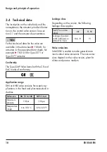
Page 18: ...The Type 3249 Valve bears both the CE and EAC marks of conformity Application range DIN or ANSI valve versions for aseptic ap plications in the food and pharmaceutical in dustries Valve size DN 15 to...

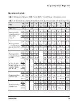
Page 19: ...115 115 d2 21 3 26 9 33 7 42 4 48 3 60 3 76 1 88 9 114 3 t 1 6 1 6 2 2 2 2 6 2 6 2 6 2 6 Welding ends for pipes according to BS 4825 L N 70 1 70 1 70 1 105 1 105 1 105 1 105 1 150 1 150 1 L S 90 90 90...

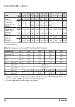
Page 20: ...80 80 80 110 110 110 110 110 155 155 H1 N 225 228 231 257 260 265 275 280 300 310 1 Not standardized Table 1 2 Dimensions for Type 3271 and Type 3277 Actuators Actuator area cm 120 240 350 700 Diaphra...

Page 21: ...0 mm travel Dimensional drawings H3 D d2 L A t H H1 H5 L D a d2 L t H H1 L H3 A t d2 L L H1 H H3 a D Type 3249 7 ball body with welding ends Type 3249 1 ball body with welding ends Type 3249 1 special...

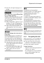
Page 22: ...e following sequence Do not open or remove the packaging until immediately before lifting to install the valve into the pipeline Leave the control valve in its transport container or on the pallet to...

Page 23: ...d bearing slings to the actuator handwheel or any other parts Observe lifting instructions see sec tion 4 3 2 A swivel hoist can be screwed into SAMSON actuators with a female thread on the top diaphr...

Page 24: ...sporting Secure slings against slipping Make sure the slings can be removed from the valve once it has been installed into the pipeline Prevent the control valve from tilting or tipping over Do not le...

Page 25: ...4 Install the valve into the pipeline see sec tion 5 3 2 5 After installation into the pipeline de pending on the type of connection e g welding joint flanged joint etc check whether the valve in the...

Page 26: ...itions Work position The work position for the control valve is the front view looking onto the operating con trols including valve accessories Plant operators must ensure that after instal lation of...

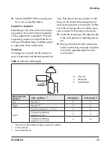
Page 27: ...rsion and mount ing position the control valve and pipeline can be supported or suspended The plant engineering company is responsible for se lecting and implementing a suitable support or suspension...

Page 28: ...e pipelines Moisture will damage the inside of the valve Check any mounted pressure gauges to make sure they function properly When the valve and actuator are al ready assembled check the tightening t...

Page 29: ...valves in the pipeline at the inlet and outlet of the plant section while the valve is being installed 2 Prepare the relevant section of the pipe line for installing the valve 3 Remove the protective...

Page 30: ...y occur through the sudden venting of the pneumatic actuator or pneumatic valve ac cessories not fitted with noise reducing fit tings Both can damage hearing Wear hearing protection when working near...

Page 31: ...ponsible for per forming the leak test and selecting the test method The leak test must comply with the requirements of the national and internation al standards that apply at the site of installa tio...

Page 32: ...vel motion The movement of the actuator stem must be linear and smooth Open and close the valve observing the movement of the actuator stem Apply the maximum and minimum con trol signals to check the...

Page 33: ...pneumatic valve accessories not fitted with noise reducing fittings Both can damage hearing Wear hearing protection when working near the valve Crush hazard arising from actuator and plug stem moving...

Page 34: ...ervice make sure the following conditions are met The valve is properly installed into the pipeline see section 5 The leak and function tests have been completed successfully see section 5 4 The preva...

Page 35: ...age hearing Wear hearing protection when working near the valve Crush hazard arising from actuator and plug stem moving Do not insert hands or finger into the yoke while the air supply is connected to...

Page 36: ...n Diaphragm damage due to uncontrolled pressure surges Avoid surges in signal pressure as they may damage the rolling diaphragm 7 1 CIP cleaning in place CIP can be performed with commonly used cleani...

Page 37: ...See associated actuator documentation Signal pressure too low Check the signal pressure Check the signal pressure line for leakage Jolting movement of the actuator and plug stem Version with adjustab...

Page 38: ...ecommended action The valve leaks to the atmosphere fugitive emissions Defective packing Replace packing see section 9 4 2 or contact our after sales service Version with adjustable packing 1 packing...

Page 39: ...cold com ponents and pipeline Valve components and the pipeline may be come very hot or cold Risk of burn injuries Allow components and pipelines to cool down or heat up Wear protective clothing and...

Page 40: ...bottom of the actu ator Before starting any work on the actuator relieve the compression from the pre loaded springs see associated actuator documentation Risk of personal injury due to residual pro...

Page 41: ...rtain intervals to prevent a possible failure before it can occur Opera tors are responsible for drawing up an in spection and test plan Our after sales service can support you in drawing up an inspec...

Page 42: ...with a plastic hammer and tighten the clamp screw again 5 Repeat this procedure several times to tighten the clamp as far as it will go 6 Screw the lock nut 6 2 and stem con nector nut 6 1 onto the pl...

Page 43: ...to the plug stem 6 using a suitable tool Observe tight ening torques Valve size Tightening torque in Nm DN NPS 15 to 25 to 1 10 32 to 100 1 to 4 70 6 Mark the side mounting position 7 Remove the plug...

Page 44: ...acking chamber using a suitable tool Renew the damaged parts and carefully clean the packing chamber 9 5 Ordering spare parts and operating supplies Contact your nearest SAMSON subsidiary or SAMSON s...

Page 45: ...safety gloves Risk of personal injury due to pressurized components and process medium escaping under pressure Do not loosen the screw of the test con nection while the valve is pressurized Risk of h...

Page 46: ...cal burns Wear protective clothing safety gloves and eye protection Diaphragm damage through the use of an incompressible medium Closing the valve when the shut off valves upstream and downstream of t...

Page 47: ...nblocking the actuator and plug stem after they have become blocked e g due to seizing up after remaining in the same position for a long time release any stored energy in the actuator e g spring comp...

Page 48: ...ated from the pipeline see section 4 3 2 Cut the pipeline in front of the weld seam Special version Undo the pipe joint depending on the type of end connection used see sec tion 5 3 2 3 Remove the val...

Page 49: ...After sales Service 2 Send an e mail u retouren samsongroup com to register the return shipment including the following information Type Article no Configuration ID Original order Completed Declaratio...

Page 50: ...50 EB 8048 EN Disposal 13 Disposal Observe local national and internation al refuse regulations Do not dispose of components lubricants and hazardous substances together with your household waste...

Page 51: ...EB 8048 EN 51 Certificates 14 Certificates The declaration of conformity in accordance with Pressure Equipment Directive 2014 68 EU is provided on the following two pages...

Page 52: ...ged steel Geh use Schmiedestahl DN 32 100 1 Pmax T 20 C 10 bar NPS 1 4 1 Pmax T 70 F 150 psi Tout type de fluides all fluids alle Fluide Vanne de r gulation passage droit globe valve Durchgangsventil...

Page 53: ...ion des lois des Etats Membres concernant la mise disposition sur le march d quipements sous pression Directive of the European Parliament and of the Council on the Harmonization of the laws of the Me...

Page 54: ...ts 15 2 Spare parts Standard version for Type 3271 and Type 3277 Actuators 1 Valve body 3 Plug 4 Bearing sleeve 5 Valve bonnet 5 3 Yoke 5 5 Travel indicator scale 5 6 Clamp 5 7 Retaining plate 5 8 Scr...

Page 55: ...asher 4 4 Test connection 4 5 Seal for test connection 5 Valve bonnet 5 2 Threaded bushing 5 3 Yoke 5 4 Screws 5 5 Travel indicator scale 5 7 Retaining plate 5 8 Screw 6 Plug stem 6 1 Stem connector n...

Page 56: ...aries The addresses of SAMSON AG its subsid iaries representatives and service facilities worldwide can be found on our website www samsongroup com or in all SAMSON product catalogs Required specifica...

Page 57: ...EB 8048 EN 57...

Page 58: ...58 EB 8048 EN...

Page 59: ...EB 8048 EN 59...

Page 60: ...2020 01 13 English SAMSON AKTIENGESELLSCHAFT Weism llerstra e 3 60314 Frankfurt am Main Germany Phone 49 69 4009 0 Fax 49 69 4009 1507 samson samsongroup com www samsongroup com EB 8048 EN...

Reviews: