EB 8332-2 EN
7-9
Start-up and configuration
1
2
3
12
13
17
21 11.1
11.2
18
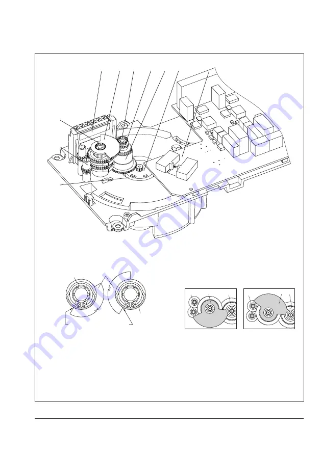
Fig. 7-6:
Installing the limit contacts
B
B
Actuator stem
Retracted
Extended
20
19
19
B
B
18
21
1
When actuator stem
retracted:
B
B
18
1
21
When actuator stem
extended:
Fig. 7-7:
Alignment of contact cam to the cam holder
Fig. 7-8:
Alignment of the contact cam unit
1
Intermediate gear
2
Spindle gear
3
Serrated ring
11.1 Spindle 1
11.2 Spindle 2
12
Actuator board
13
Bearing sleeve
17
Terminal board
18
Adjustment gear
19
Contact cam
20
Cam holder
21
Contact cam unit
Summary of Contents for 3375
Page 6: ...Contents EB 8332 2 EN ...
Page 12: ...1 6 EB 8332 2 EN ...
Page 40: ...5 16 EB 8332 2 EN ...
Page 45: ...EB 8332 2 EN 6 5 Operation Fig 6 3 Housing cover of special version with three key operation ...
Page 46: ...6 6 EB 8332 2 EN ...
Page 63: ...EB 8332 2 EN 8 5 Setup 1 2 Fig 8 2 Manual override ...
Page 72: ...8 14 EB 8332 2 EN ...
Page 78: ...9 6 EB 8332 2 EN ...
Page 80: ...10 2 EB 8332 2 EN ...
Page 82: ...11 2 EB 8332 2 EN ...
Page 84: ...12 2 EB 8332 2 EN ...
Page 86: ...13 2 EB 8332 2 EN ...
Page 88: ...14 2 EB 8332 2 EN ...
Page 90: ...15 2 EB 8332 2 EN Certificates EU declaration of conformity ...
Page 122: ...16 32 EB 8332 2 EN ...
Page 125: ...EB 8332 2 EN 17 3 Service key number 1732 Customized key number ...
Page 126: ...17 4 EB 8332 2 EN ...
Page 127: ......
Page 128: ......
Page 129: ......


