background image

Series 430

Pneumatic Indicating Controllers
Type 3430

Fig. 1 · Controller stations

Mounting and
Operating Instructions

EB 7030 EN

Edition October 2010

Type 3432 Controller Station

– with Type 3435 Transmitter Module for Pressure
– with Type 3436 Transmitter Module for Temperature
– with Type 3438 Transmitter Module for Temperature (Pt 100)
– for standardized signals
Version shown with lockable door and integrated
Type 3436 Transmitter Module for Temperature

Type 3431 Controller Station

– for standardized signals

Summary of Contents for 3430

Page 1: ...e 3432 Controller Station with Type 3435 Transmitter Module for Pressure with Type 3436 Transmitter Module for Temperature with Type 3438 Transmitter Module for Temperature Pt 100 for standardized sig...

Page 2: ...adjusting the controller s zero point 10 4 Construction 11 5 Principle of operation 11 5 1 Transmitter modules 11 5 2 Controller station 12 5 3 Controller modules 14 5 3 1 Type 3433 Controller Modules...

Page 3: ...g to these mounting and operating instructions trained personnel is referred to as individuals who are able to judge the work they are assigned to and recognize possible dangers due to their specializ...

Page 4: ...as been re leased and the indicating unit 5 has been opened out The settings for operating action turnboard A and air supply turnboard B must be performed prior to commissioning 4 Unscrew the mounting...

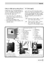
Page 5: ...ontroller Module Air supply Oper action Setting or modifying the operating direction Unfasten the screw in turnboard A Fig 2 and lift it off together with the turnboard If necessary lever the board at...

Page 6: ...related to the con trolled system that is being tuned section 3 1 2 1 4 Reset time Tn Controller versions with integral action com ponent require the reset time to be set at the restriction 10 The set...

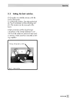
Page 7: ...lock 4 Fig 2 and open out the indicating unit 5 The contacts can be accessed at the back Adjust proximity switches by placing a screwdriver in the clamps between 0 and 100 of the reference scale and m...

Page 8: ...fficient results in most cases 1 Apply supply air 1 4 0 1 bar 2 Set the proportional action coefficient KP to a low value at the comparator 3 Set Tn restrictor to its maximum value and Tv to its lowes...

Page 9: ...educe KP and increase Tn Repeat these steps if necessary until the control loop shows a satisfactory perfor mance Leave enough time in between set ting to allow the controller to stabilize 3 1 1 Setti...

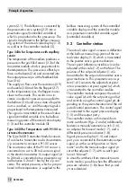
Page 10: ...djusting the set point adjuster 1 4 The switch 1 6 can only be set to automatic after the differential pressure indicator 1 8 is at zero Set the set point again to the required value 3 3 Smooth change...

Page 11: ...ressure indicator The controller station must be equipped with an additional module for wint wext change over when used for applications as a com bined fixed set point controller and follower controll...

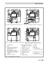
Page 12: ...between 0 2 and 1 bar by the i p con verter The output pressure which is propor tional to the temperature is supplied to the bellows measuring system of the controlled variable display and the contro...

Page 13: ...k Type 3432 with manual automatic switch 1 6 supply pressure regulator 1 9 and i p converter Type 3432 with Type 3435 Transmitter for Pressure Type 3432 with Type 3436 Transmitter for Temperature 1 8...

Page 14: ...e initial value and the output pres sure yA reaches the value related to the con trolled variable x and the proportional ac tion coefficient Kp set at the screw Outside of the controller module yA is...

Page 15: ...adjuster is used in place of the integral element Type 3433 3 PID Controller Module corresponds to Type 3433 2 Additionally it contains a derivative element which produces the rate action with approx...

Page 16: ...e used as a P controller with operating point adjustment or as a PI controller The structure is the same as that of the PI and P controller module Type 3433 6 PD PID Controller Module with PD PID sele...

Page 17: ...n of the force switch continues to change until the controller output pressure reaches a value which is related to the con trolled variable x and the adjusted propor tional action coefficient Kp i e u...

Page 18: ...fitted with a wint wext selector switch The associated set point adjuster and differ ential pressure indicator allow a smooth switchover when the indicator is at zero Re fer to section 3 3 5 4 3 Supp...

Page 19: ...variable x which acti vate associated proximity switches When the metal tag moves into the field of the inductive pick up it is highly resistive and when the metal tag moves outside of the field it is...

Page 20: ...llation Fig 11 Installation dimensions of Type 3432 Controller Station 160 10 10 124 7 28 13 160 69 28 45 40 13 228 8 228 8 241 29 26 27 8 938 26 27 8 938 5 36 192 30 31 30 30 16 19 5 G 300 400 300 42...

Page 21: ...61554 DIN 43700 Type 3432 Panel cut out 188 1 x 255 1 mm Required panel mounting kit Order no 1400 6300 Type 3431 Panel cut out 188 1 x 138 1 mm Required panel mounting kit Order no 1400 6303 Protect...

Page 22: ...led in any position However the entire length of the sensor must be immersed in the medium to be controlled Choose a point of installation where over heating or noticeable time delays cannot oc cur Ru...

Page 23: ...080 4884 G Order no 1080 4885 Install as described above Tighten clamping nut instead of coupling nut Thermowell with thread PN 63 G Order no 1080 4888 G Order no 1080 4889 Use a thermowell when the n...

Page 24: ...h the controller station 38 Output y Manipulated variable Output signal of the controller to operate the control valve or positioner 8 9 Supply Supply air Supply air 1 4 0 1 bar or 2 to 12 bar for the...

Page 25: ...pressure gauge 4 Controller stations with a manual auto matic selector switch have a test connec tion yellow inside the indicating unit Use the enclosed test connector for this version Fig 15 4 Unscre...

Page 26: ...r U0 Ii or I0 Pi or P0 Ci or C0 and Li or L0 Note The terminal assignment spe cified in the Mounting and Opera ting Instructions must be adhered to Reversing the assignment of the elec trical terminal...

Page 27: ...o output signal un screw the restriction 7 Figs 2 and 17 on the left side underneath the comparator and clean or replace it order no 1390 0183 Pull out the filter if need be and replace it order no 05...

Page 28: ...12 and replace it with a selector switch with operating point adjuster 13 and Tn restriction 10 P into PD Unscrew cover plate 14 1 Take out O ring 14 3 and insert two O rings 14 4 in its place Screw o...

Page 29: ...g point Fasten the plate with restriction 15 in place of the adjuster for operating point 12 Note We recommend replacing old O rings as well as the filter in the restriction 7 with new ones EB 7030 EN...

Page 30: ...unting screws on the bottom of the controller station and re move the transmitter module 4 Mount the new transmitter in the reverse order On attaching the hoses to ports x and Z it is important not to...

Page 31: ...ansmitter itself must be installed in areas of Zone 1 or Zone 2 Caution Observe the following for installations in po tentially explosive atmospheres On install ing and performing service work on the...

Page 32: ...r 3437 1 Control Mode Selector Switch 3437 2 Manual auto Transfer Switch 3437 3 Output 0 2 to 1 bar 3 to 15 psi Max 0 02 to 1 35 bar Supply air Standard version Supply air 1 4 bar 0 1 bar 20 psi 1 5 p...

Page 33: ...le consisting of Temperature Transmitter TTH200 E1H with Type 6112 22 i p Converter Module Electric Temperature Transmitter TTH200 E1H Input Pt 100 resistance thermometer RTD Measuring ranges 30 to 60...

Page 34: ...2 i p Transmitter Module Type 6112 02 without explosion protection Input impedance 200 W and 5 9 mH Type 6112 22 with explosion protection 1 Intrinsically safe input circuit Input impedance 200 W and...

Page 35: ...EB 7030 EN 35...

Page 36: ...36 EB 7030 EN...

Page 37: ...EB 7030 EN 37...

Page 38: ...38 EB 7030 EN...

Page 39: ...EB 7030 EN 39...

Page 40: ...40 EB 7030 EN...

Page 41: ...EB 7030 EN 41...

Page 42: ...42 EB 7030 EN...

Page 43: ...EB 7030 EN 43...

Page 44: ...44 EB 7030 EN...

Page 45: ...EB 7030 EN 45...

Page 46: ...46 EB 7030 EN...

Page 47: ...EB 7030 EN 47...

Page 48: ...48 EB 7030 EN...

Page 49: ...EB 7030 EN 49...

Page 50: ...50 EB 7030 EN...

Page 51: ...EB 7030 EN 51...

Page 52: ...SAMSON AG MESS UND REGELTECHNIK Weism llerstra e 3 60314 Frankfurt am Main Germany Phone 49 69 4009 0 Fax 49 69 4009 1507 Internet http www samson de EB 7030 EN S Z 2010 11...

Reviews: