background image

The condition is only active when

Activa-

tion tolerance band control is set to
"On".

During the course of the test, the following
parameters are changed as specified:

4

Lower x-range value (Code 8): 0 %

4

Upper x-range value (Code 9): 100 %

4

w-ramp OPEN/CLOSED (Codes 21/22):
variable

The data can be reset in the [Status mes-
sages] folder under Reset.

2.1

Changing ESD parameters
and starting the partial
stroke test

To change ESD parameters using
TROVIS-VIEW 3, proceed as follows:
1. Enter ESD code (see section 1.3.2).

If the positioner is not operated and no
data are modified by an operating
program (DTM or TROVIS-VIEW 3) for
15 minutes, the positioner is locked
again. To make additional changes, the
ESD code needs to be entered again.

2. In the [Positioner] folder under Oper-

ating mode, set the

Target mode param-

eter to “Emergency Shut Down“.

3. In the [Emergency Shut Down] folder, set

the

ESD operating mode parameter to

“On“.

4. In the [Emergency Shut Down] folder, se-

lect the

ESD operating mode parameter

to “ESD Man“.
The positioner alternately displays
“ESd”, the

Manual reference variable w,

and “MAN“.

5. Set the parameters in the [Emergency

Shut Down] folder as desired.

The further course of action depends on
whether the test is to be started manually
(–> Test started manually) or performed au-
tomatically at certain intervals according to
schedule (–> Test started automatically ac-
cording to schedule).

Test started manually

6. Right-click the

Start step response pa-

rameter and select Execute from the con-
text-sensitive menu.

7. The test will start after the “Warning.

During test start the control valve departs
from its current position at full travel! Ex-
ecute test?“ message has been con-
firmed.
The positioner displays “tEst d4“.

Test started automatically according to
schedule

6. Set the

Auto test time parameter to the

desired interval at which the partial
stroke test is to be repeated.
If

Auto test time is set to “0”, the test is

not performed.

7. In

ESD operating mode, select “ESD

Auto“.
The test is performed at the

Auto test

time interval. The first test is started
when the interval has elapsed for the
first time.
After switching the operating mode and
returning to ESD Auto mode, the

Auto

test time interval starts again.
The

Time until the next automatic ESD

12

EB 8388-1 EN

ESD functions

Summary of Contents for 3730-3 ESD

Page 1: ...ectropneumatic Positioner Type 3730 3 ESD Version With HART communication Mounting and Operating Instructions EB 8388 1 EN Firmware version 1 4x Edition November 2006 Fig 1 ESD mode in SAMSON TROVIS V...

Page 2: ...ting the diagnostic ESD log 7 2 ESD functions 8 2 1 Changing ESD parameters and starting the partial stroke test 12 2 1 1 On site operation 13 2 2 Analyzing measured data 13 2 2 1 Condensed state Faul...

Page 3: ...s active the positioner keeps the attached valve to a set position e g open The valve does not per form any control tasks anymore In AUTO operating mode the positioner can be used to control the attac...

Page 4: ...ording to sched ule ESD Auto Partial stroke test The partial stroke test integrated into the positioner can prevent a normally open valve or a valve in its end position from seizing up or getting jamm...

Page 5: ...ositioner 1 3 1 Converting TROVIS VIEW 3 The TROVIS VIEW 3 version must match the software version of the positioner When establishing communication or ex changing data between the PC and the position...

Page 6: ...ng mode The ESD code can be found on page 21 Remove the code or make it unreadable to prevent unauthorized use Entering the code on the positioner Default OFF Turn Code 3 Press Turn ON Press Display s...

Page 7: ...ion Select Print in the File menu to add further information 1 In the File menu select Print Options to choose the scope of the diagnostic log After installing updating the TROVIS VIEW software custom...

Page 8: ...SD mode parameter in the Diagnosis folder under Emergency Shut Down is set to On In ESD mode the safety shut off valve is specifically moved to the set point of the valve working range parameter Requi...

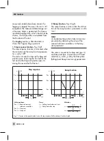
Page 9: ...before the test starts Starting from the Step start position pos 2 the valve moves to the defined end position Step end parameter pos 3 The valve re mains in this position for the time defined by the...

Page 10: ...ction Fig 2 right The ramp function is active when the Activa tion of the ramp function parameter is set to On Note A step before the partial stroke test can be prevented by allocating the value of th...

Page 11: ...e value falls below the adjusted valve position range 10 to 110 The condition is only active when Activa tion x control is set to On 4 y control value The test is cancelled when the value falls below...

Page 12: ...s ESd the Manual reference variable w and MAN 5 Set the parameters in the Emergency Shut Down folder as desired The further course of action depends on whether the test is to be started manually Test...

Page 13: ...when the positioner is in ESD Man operating mode 4 Setting the reference variable Manual w using Code 1 4 Setting the ESD parameters using Code 49 see section 2 5 Starting the partial stroke test 1 Se...

Page 14: ...ead time s 4 T63 s 4 T98 s 4 Rise time s 4 Settling time s 2 2 1 Condensed state Fault alarm output The Fault alarm output parameter allows you to define which type of alarm is issued by the hardware...

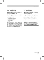
Page 15: ...easured values of the parame ters determined during the partial stroke test are listed in the Measured data folder 2 4 Resetting ESD TROVIS VIEW 3 Diagnosis Emergency Shut Down Reset ESD Using the Res...

Page 16: ...l angle is displayed in when the positioner is initialized Otherwise the sensor position in relation to the central axis is indicated in degrees 3 Unlocking the positioner configuration OFF ON ESC OFF...

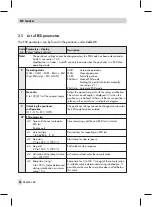
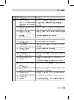
Page 17: ...0 0 0 The test is cancelled when the valve position falls below this value E2 Activation y control On Off Off Activates or deactivates y monitoring Activation only makes sense when the partial stroke...

Page 18: ...led x values outside the toler ance band occurred F5 Max test time exceeded Test not completed within the maximum test duration and therefore cancelled F6 Test manually cancelled Test cancelled by the...

Page 19: ...no further settings need to be entered EB 8388 1 EN 19 EXPERT test functions Operating mode Code 0 EXPERT functions Test requirements AUtO As in EB 8388 EN MAN ESD mode ESD Man Data logger Statistica...

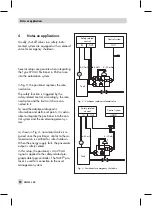
Page 20: ...the con trol system and the asset management sys tem As shown in Fig 4 no solenoid valve is re quired since the positioner similar to the so lenoid valve is certified for safe shutdown When the energy...

Page 21: ...tegrated into the positioner terminals 81 82 is used to gether with an existing external solenoid valve to trigger the data logger EB 8388 1 EN 21 Notes on applications ESD code 1732 24 V 4 20 mA 81 8...

Page 22: ...22 EB 8388 1 EN...

Page 23: ...EB 8388 1 EN 23...

Page 24: ...SAMSON AG MESS UND REGELTECHNIK Weism llerstra e 3 60314 Frankfurt am Main Germany Phone 49 69 4009 0 Fax 49 69 4009 1507 Internet http www samson de EB 8388 1 EN 2007 01...

Reviews: