2.6
Reversing amplifier for
double-acting actuators
For the use with double-acting actuators, the
positioner must be fitted with a reversing
amplifier, e.g. the SAMSON Type 3710 Re-
versing Amplifier (see Mounting and Oper-
ating Instructions EB 8392 EN).
If a different reversing amplifier (item no.
1079-1118 or 1079-1119) is used, follow
the mounting instructions described in sec-
tion 2.6.1.
The following applies to all reversing am-
plifiers:
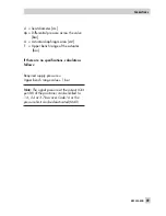
The output signal pressure of the positioner
is supplied at the output
A
1
of the reversing
amplifier. An opposing pressure, which
equals the required supply pressure when
added to the pressure at
A
1
, is applied at
output
A
2
.
The rule
A
1
+
A
2
=
Z
applies.
A
1
: Output
A
1
leading to the signal pressure
connection at the actuator which opens the
valve when the pressure increases
A
2
: Output
A
2
leading to the signal pressure
connection at the actuator which closes the
valve when the pressure increases
4
Set slide switch on positioner to
AIR TO OPEN
.
2.6.1 Reversing amplifier
(1079-1118 or 1079-1119)
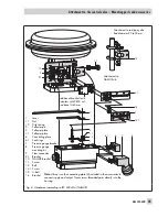
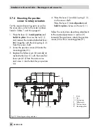
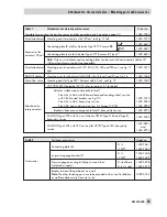
1. Mount the connecting plate (6) from the
accessories in Table 4 to the positioner.
Make sure that both O-rings (6.1) are
seated correctly.
2. Thread the special nuts (1.3) from the
accessories of the reversing amplifier
into the boreholes of the connecting
plate.
3. Insert the gasket (1.2) into the recess of
the reversing amplifier and push both
the hollowed special screws (1.1) into
the connecting boreholes
A
1
and
Z
.
4. Place the reversing amplifier onto the
connecting plate (6) and screw tight us-
ing both the special screws (1.1).
5. Use a screwdriver (8 mm wide) to screw
the enclosed filters (1.6) into the con-
necting boreholes
A
1
and
Z
.
NOTICE
The sealing plug (1.5) in the Type 3730
Positioner should not be unscrewed out of
the reversing amplifier.
The rubber seal (1.4) is not required and
can be removed when the sealing plug is
used.
6. Set to
OFF
after initialization in Code 16
(pressure limit)
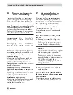
Pressure gauge attachment
The mounting sequence shown in Fig. 15 re-
mains unchanged. Screw a pressure gauge
bracket onto the connections
A
1
and
Z
.
Pressure gauge
G ¼
1400-7106
bracket:
¼ NPT
1400-7107
Pressure gauges for supply air Z and output
A
1
as listed in Tables 1 to 5.
38
EB 8384-4 EN
Attachment to the control valve – Mounting parts and accessories
Summary of Contents for 3730-4
Page 2: ...2 EB 8384 4 EN...
Page 127: ......
Page 188: ...188 EB 8384 4 EN...
Page 189: ...EB 8384 4 EN 189...
Page 190: ...190 EB 8384 4 EN...
Page 191: ...EB 8384 4 EN 191...
Page 192: ...192 EB 8384 4 EN...
Page 193: ...EB 8384 4 EN 193...
Page 194: ...194 EB 8384 4 EN...
Page 195: ...EB 8384 4 EN 195...
Page 196: ...196 EB 8384 4 EN...
Page 197: ...EB 8384 4 EN 197...
Page 198: ...198 EB 8384 4 EN...
Page 199: ...EB 8384 4 EN 199...
Page 206: ...206 EB 8384 4 EN...
Page 207: ...EB 8384 4 EN 207...
Page 208: ...208 EB 8384 4 EN...
Page 209: ...EB 8384 4 EN 209...
Page 210: ...210 EB 8384 4 EN...
Page 211: ...EB 8384 4 EN 211...


