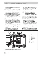
2.7.4 Mounting the position
sensor to rotary actuators
For the required mounting parts as well as
the accessories, refer to the order numbers
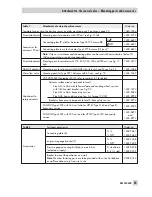
listed in Tables 7 and 8 on page 45.
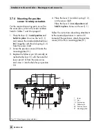
1. Place the lever (1)
in mid-position
and
hold it in place
. Unscrew the nut (1.1)
and remove the standard attached lever
M
(1) together with the disk spring (1.2)
from the sensor shaft.
2. Screw the position sensor (20) onto the
mounting plate (21).
3. Replace the follower pin (2) normally at-
tached to the lever (1) with the metal fol-
lower pin (Ø 5) from the accessories
and screw it into the hole for pin position
90°.
4. Place the lever (1) and disk spring (1.2)
on the sensor shaft.
Place the lever (1)
in mid-position
and
hold it in place
. Screw on the nut (1.1).
Follow the instructions describing attachment
to the standard positioner in section 2.5
Instead of the positioner, attach the position
sensor (20) with its mounting plate (21).
44
EB 8384-4 EN
Attachment to the control valve – Mounting parts and accessories
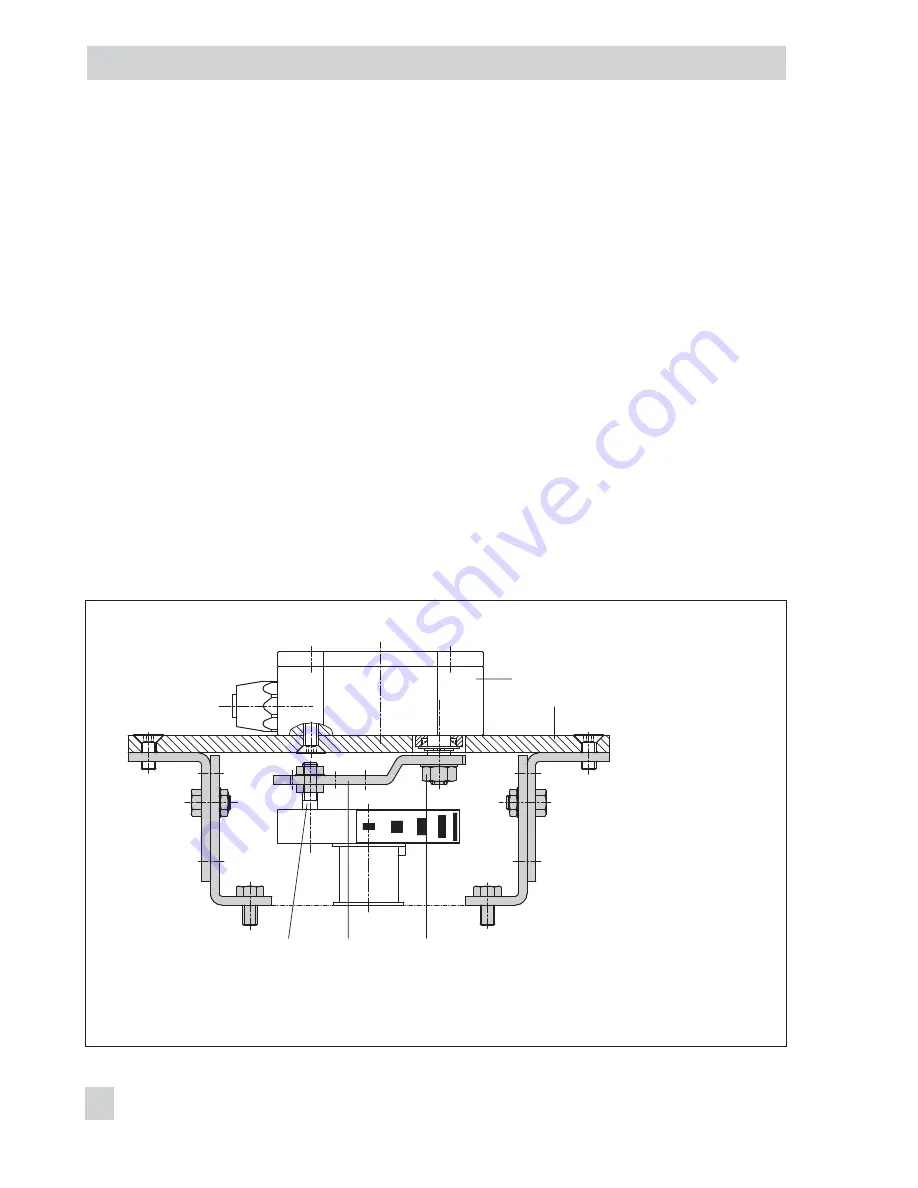
Fig. 20 · Mounting on rotary actuators
20
21
2
1
1.1, 1.2
1
Lever
1.1 Nut
1.2 Disk spring
2
Follower pin
20 Position sensor
21 Mounting plate
Summary of Contents for 3730-4
Page 2: ...2 EB 8384 4 EN...
Page 127: ......
Page 188: ...188 EB 8384 4 EN...
Page 189: ...EB 8384 4 EN 189...
Page 190: ...190 EB 8384 4 EN...
Page 191: ...EB 8384 4 EN 191...
Page 192: ...192 EB 8384 4 EN...
Page 193: ...EB 8384 4 EN 193...
Page 194: ...194 EB 8384 4 EN...
Page 195: ...EB 8384 4 EN 195...
Page 196: ...196 EB 8384 4 EN...
Page 197: ...EB 8384 4 EN 197...
Page 198: ...198 EB 8384 4 EN...
Page 199: ...EB 8384 4 EN 199...
Page 206: ...206 EB 8384 4 EN...
Page 207: ...EB 8384 4 EN 207...
Page 208: ...208 EB 8384 4 EN...
Page 209: ...EB 8384 4 EN 209...
Page 210: ...210 EB 8384 4 EN...
Page 211: ...EB 8384 4 EN 211...


