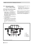
Note:
The power supply for the positioner
can be supplied either over the connection
to the fieldbus segment or over a DC voltage
source (9 to 32 V) connected to the bus ter-
minals in the positioner.
You are required to
observe the relevant regulations for use in
hazardous areas
.
Accessories:
Cable gland M20 x 1.5
Order no.
Black plastic
(6 to 12 mm clamping range)
8808-1011
Blue plastic
(6 to 12 mm clamping range)
8808-1012
Nickel-plated brass
(6 to 12 mm clamping range)
1890-4875
Nickel-plated brass
(10 to 14 mm clamping range)
1922-8395
Stainless steel 1.4305
(8 to 14.5 mm clamping range)
8808-0160
EMC cable
Nickel-plated brass
8808-0143
Adapter M20 x 1.5 to ½ NPT
Aluminum, powder paint coated
0310-2149
Stainless steel
1400-7114
Bus line
Route the two-wire bus line to the screw ter-
minals marked "IEC 1158-2", whereby no
polarity has to be observed.
Refer to the PROFIBUS-PA User + Installation
Guide (PNO document 2.092) for more in-
formation.
Note:
To connect the limit switch, binary in-
puts and forced venting, an additional cable
EB 8384-4 EN
51
Connections
u
Option
+81 -82
IEC 1158-2
+87 -88
+85 -86
+41 -42
A
B
24 V DC
BE1
BE2
G
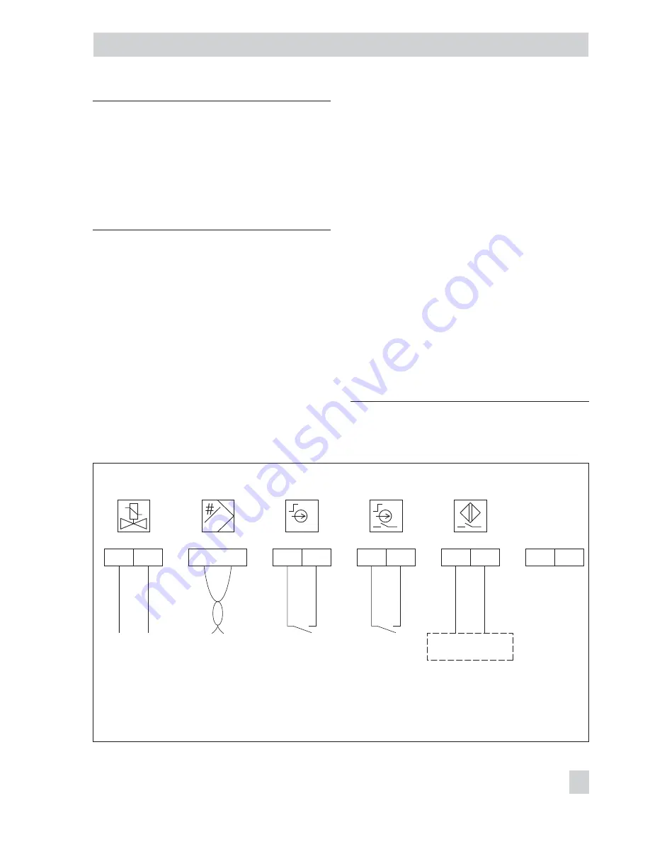
Fig. 21 · Electrical connections
Solenoid valve
Forced venting
(optional)
Binary contacts
Bus line
Inductive limit switch
(optional)
Switch. amplifier
EN 60947-5-6
In preparation
(optional)
Summary of Contents for 3730-4
Page 2: ...2 EB 8384 4 EN...
Page 127: ......
Page 188: ...188 EB 8384 4 EN...
Page 189: ...EB 8384 4 EN 189...
Page 190: ...190 EB 8384 4 EN...
Page 191: ...EB 8384 4 EN 191...
Page 192: ...192 EB 8384 4 EN...
Page 193: ...EB 8384 4 EN 193...
Page 194: ...194 EB 8384 4 EN...
Page 195: ...EB 8384 4 EN 195...
Page 196: ...196 EB 8384 4 EN...
Page 197: ...EB 8384 4 EN 197...
Page 198: ...198 EB 8384 4 EN...
Page 199: ...EB 8384 4 EN 199...
Page 206: ...206 EB 8384 4 EN...
Page 207: ...EB 8384 4 EN 207...
Page 208: ...208 EB 8384 4 EN...
Page 209: ...EB 8384 4 EN 209...
Page 210: ...210 EB 8384 4 EN...
Page 211: ...EB 8384 4 EN 211...

