4
Operation
Note:
A summary about operating and start
up can be found in section 8 on page 79.
4.1
Operator controls and
readings
Rotary pushbutton
The positioner is mainly operated with the
rotary pushbutton.
Turn the
button to select and set codes,
parameter and values. Press to confirm.
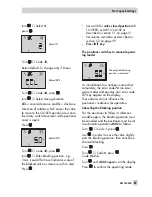
Slide switch AIR TO OPEN or AIR TO CLOSE
4
AIR TO OPEN applies when the
increasing signal pressure opens the
valve
4
AIR TO CLOSE applies when the
increasing signal pressure closes the
valve
The signal pressure is the air pressure at the
output of the positioner which is applied to
the actuator.
For positioners with an attached reversing
amplifier for double-acting rotary actuators
(section 2.6): switch position AIR TO OPEN.
For checking purposes:
After successfully completing initialization,
the positioner display should read 0 % when
the valve is closed and 100 % when the
valve is open. If this is not the case, change
the slide switch position and re-initialize the
positioner.
The switch position is prompted prior to an
initialization. After an initialization has been
completed, changing the switch position
does not have any effect on the operation of
the positioner.
Volume restriction Q
The volume restriction is used to adapt the
air delivery to the actuator size. Two fixed
settings are possible depending on how the
air is routed at the actuator:
4
For actuators smaller than 240 cm² with
a loading pressure connection at the side
(Type 3271-5), set restriction to MIN
SIDE.
4
For a connection at the back (Type
3277-5), set restriction to MIN BACK.
4
For actuators 240 cm² and larger, set to
MAX SIDE for a side connection and to
MAX BACK for a connection at the back.
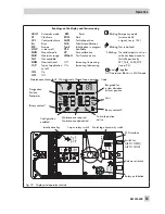
Readings on the display
A self test is performed automatically
(
tEStinG
runs across the display) when the
positioner starts up for the first time after the
electrical auxiliary power has been con-
nected.
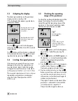
Icons appear on the LC display that are as-
signed to parameters, codes and functions.
The bar elements in the operating modes
manual
and automatic
indicate the
system deviation that depends on the sign
(+/–) and the value. One bar element ap-
pears per 1 % system deviation.
If the device has not yet been initialized (see
section 4.3.1), the lever position in degrees
in relation to the longitudinal axis is indi-
cated instead of the system deviation. One
bar element corresponds to approximately a
5° angle of rotation.
If the fifth element blinks (value displayed
> 30°), the permissible angle of rotation has
been exceeded. Lever and pin position must
be checked.
54
EB 8384-4 EN
Operation
Summary of Contents for 3730-4
Page 2: ...2 EB 8384 4 EN...
Page 127: ......
Page 188: ...188 EB 8384 4 EN...
Page 189: ...EB 8384 4 EN 189...
Page 190: ...190 EB 8384 4 EN...
Page 191: ...EB 8384 4 EN 191...
Page 192: ...192 EB 8384 4 EN...
Page 193: ...EB 8384 4 EN 193...
Page 194: ...194 EB 8384 4 EN...
Page 195: ...EB 8384 4 EN 195...
Page 196: ...196 EB 8384 4 EN...
Page 197: ...EB 8384 4 EN 197...
Page 198: ...198 EB 8384 4 EN...
Page 199: ...EB 8384 4 EN 199...
Page 206: ...206 EB 8384 4 EN...
Page 207: ...EB 8384 4 EN 207...
Page 208: ...208 EB 8384 4 EN...
Page 209: ...EB 8384 4 EN 209...
Page 210: ...210 EB 8384 4 EN...
Page 211: ...EB 8384 4 EN 211...


