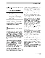
ator and take several minutes.
Positioners with EXPERT
+
diagnostic func-
tions start plotting the reference graphs after
the initialization process has been com-
pleted. See note at the end of this section.
WARNING!
During the initialization, the control
valve moves through its entire tra-
vel/angle of rotation range. Therefo-
re, do not start initialization while a
process is running, but only during
start-up, when all shut-off valves are
closed.
Note:
The initialization procedure
can be interrupted while running by
pressing
.
StOP
appears three se-
conds long and the positioner then
moves to the fail-safe position.
The fail-safe position can be cance-
led again over Code
0
.
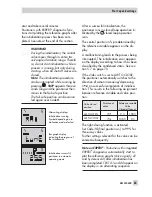
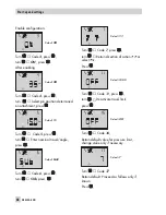
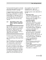
Alternating displays
Initialization running
Symbol depending on in-
itialization mode selected
Bar graph display
indicating the progress of
the initialization
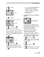
Initialization successful,
positioner in automatic
operating mode
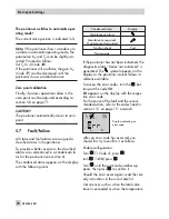
After a successful initialization, the
positioner runs in closed-loop operation in-
dicated by the
closed-loop operation
icon.
The control position in % predetermined by
the reference variable appears on the dis-
play.
A malfunctioning leads to the process being
interrupted. The initialization error appears
on the display according to how it has been
classified by the condensed status. See sec-
tion 5.7 on page 70.
If the slide switch is set to AIR TO CLOSE,
the positioner automatically switches to the
direction of action increasing/decreasing
(
äæ
) on successful completion of initializa-
tion. This results in the following assignment
between reference variable and valve posi-
tion:
Valve closed
position
Direction of
action
Reference variable
Valve
Closed at Open at
AIR TO OPEN
ää
0 %
100 %
AIR TO CLOSE
äæ
100 %
0 %
The tight-closing function is activated.
Set Code
15
(final position w>) to 99 % for
three-way valves.
Further settings relevant for the valve can be
entered subsequently.
Note on EXPERT
+
:
Positioner with integrated
EXPERT
+
diagnostics automatically start to
plot the reference graphs (drive signal y d1
and hysteresis d2) after initialization has
been completed. TEST d1 and d2 appear on
the display in an alternating sequence.
EB 8384-4 EN
63
Start-up and settings
%
Summary of Contents for 3730-4
Page 2: ...2 EB 8384 4 EN...
Page 127: ......
Page 188: ...188 EB 8384 4 EN...
Page 189: ...EB 8384 4 EN 189...
Page 190: ...190 EB 8384 4 EN...
Page 191: ...EB 8384 4 EN 191...
Page 192: ...192 EB 8384 4 EN...
Page 193: ...EB 8384 4 EN 193...
Page 194: ...194 EB 8384 4 EN...
Page 195: ...EB 8384 4 EN 195...
Page 196: ...196 EB 8384 4 EN...
Page 197: ...EB 8384 4 EN 197...
Page 198: ...198 EB 8384 4 EN...
Page 199: ...EB 8384 4 EN 199...
Page 206: ...206 EB 8384 4 EN...
Page 207: ...EB 8384 4 EN 207...
Page 208: ...208 EB 8384 4 EN...
Page 209: ...EB 8384 4 EN 209...
Page 210: ...210 EB 8384 4 EN...
Page 211: ...EB 8384 4 EN 211...

