background image

10

Maintenance

The positioner does not require any mainte-
nance.

There are filters with a 100 µm mesh size in
the pneumatic connections for supply and
output which can be removed and cleaned,
if required.

The maintenance instructions of any up-
stream supply air pressure reducing stations
must be observed.

11

Servicing explosion-
protected devices

If a part of the device on which the explo-
sion protection is based needs to be ser-
viced, the device must not be put back into
operation until a qualified inspector has as-
sessed it according to explosion protection
requirements, has issued an inspection cer-
tificate or given the device a mark of confor-
mity.

Inspection by a qualified inspector is not re-
quired if the manufacturer performs a rou-
tine test on the device prior to putting it back
into operation. The passing of the routine
test must be documented by attaching a
mark of conformity to the device. Replace
explosion-protected components only by
original, routine-tested components from the
manufacturer.

Devices that have already been operated
outside hazardous areas and are intended
for future use inside hazardous areas must
comply with the safety requirements placed
on serviced devices. Before being used in-

side hazardous areas, test the devices ac-
cording to the specifications for servicing
explosion-protected devices.

Read section 13 for maintenance, calibra-
tion and adjustment work inside and outside
hazardous areas.

12

Firmware update (serial
interface)

Firmware updates on positioners currently in
operation can be performed as follows:

When updates are performed by a service
employee appointed by SAMSON, the up-
date is confirmed on the positioner by the
test mark assigned by SAMSON’s Quality
Assurance.

In all other cases, only persons from the
plant operator with written approval may
perform updates. This person must confirm
the update on the positioner.

Laptops and PCs connected to the power
supply must use an additional safety barrier.

This does not apply to laptops in battery op-
eration. In this case, it is assumed that a bat-
tery-powered laptop runs briefly for soft-
ware programming or for testing purposes.

a) Updates outside the hazardous area:

Remove the positioners from the plant
and update them outside the hazardous
area.

b) Updates on site:

Updates on site are only permitted after
the plant operator has presented a sig-
ned hot work permit.

84

EB 8384-4 EN

Maintenance

Summary of Contents for 3730-4

Page 1: ...e 3730 4 Electropneumatic Positioner with PROFIBUS PA communication Mounting and Operating Instructions EB 8384 4 EN 1300 1613 Firmware version K 1 17 R 1 46 Edition July 2017 Fig 1 Type 3730 4 New de...

Page 2: ...2 EB 8384 4 EN...

Page 3: ...n sensor with direct attachment 40 2 7 2 Mounting the position sensor with attachment according to IEC 60534 6 42 2 7 3 Mounting the position sensor to Type 3510 Micro flow Valve 43 2 7 4 Mounting the...

Page 4: ...ick start up guide 79 8 1 Mounting 79 8 2 Start up 80 8 3 Initialization 81 8 3 1 Simplest method MAX 81 8 3 2 Precise method NOM 81 8 3 3 Manual method MAN 82 9 Retrofitting an inductive limit switch...

Page 5: ...4 5 Diagnostics with PROFIBUS DP protocol 104 14 6 Acyclic data exchange 110 15 Appendix 111 15 1 Code list 111 15 2 Parameter list 127 16 Dimensions in mm 184 16 1 Fixing levels according to VDI VDE...

Page 6: ...acc to PROFIBUS PA Profile 3 02 added It allows a Type 3785 Positioner Profile 2 0 and Profile 3 0 to be directly replaced with a Type 3730 4 Positioner in the compatability mode see page 87 K 1 16 T...

Page 7: ...ed versions 4 Any hazards that could be caused by the process medium the operating pressure the signal pressure or by moving parts of the control valve are to be prevented by means of the appropriate...

Page 8: ...0 C IP66 8 Additional equipment Inductive limit switch Without SJ2 SN NC contact 0 1 Solenoid valve Without With 24 V DC 0 4 External position sensor Without With 0 0 1 0 0 Binary input Without Floati...

Page 9: ...ite to 1 4 2 4 or 3 7 bar A constant air stream to the atmosphere is created by the flow regulator 9 with a fixed set point The air stream is used to purge the inside of the housing as well as to opti...

Page 10: ...ed over the PROFIBUS PA net work Version with external position sensor In this version only the sensor is mounted to the control valve The positioner is located separately from the valve The connectio...

Page 11: ...hin the initialized travel angle of rotation travel can be restricted to 1 5 at the maximum Bus connection Fieldbus interface acc to IEC 61158 2 bus powered Field device acc to FISCO Fieldbus Intrinsi...

Page 12: ...up to 2000 Hz and 4 g acc to IEC 770 Electromagnetic compatibility Complying with requirements of EN 61000 6 2 EN 61000 6 3 EN 61326 1 and NAMUR Recommendation NE 21 Electrical connection One M20 x 1...

Page 13: ...ing amplifier acc to EN 60947 5 6 SJ2 SN proximity switch Measuring plate not detected 3 mA Measuring plate detected 1 mA External position sensor Travel Same as Type 3730 Positioner Cable 10 m with M...

Page 14: ...Number Date Valid until RU C DE 08 B 00697 2014 12 15 2019 12 14 1Ex ia IIC T6 Ex tb IIIC T80 C Db X IP66 41 IECEx Number Date PTB 06 0054 2006 11 02 Ex ia IIC T6 41 NEPSI Number Date Valid until GYJ1...

Page 15: ...achment to Type 3277 Actuator Type 3277 5 and 3277 Actuators Actuator size cm Rated travel mm Adjustment range at positioner Min Travel Max Required lever Assigned pin position 120 7 5 5 0 25 M 25 120...

Page 16: ...w 1400 6822 Connecting plate new for Actuator Type 3277 5xxxxxx 01 new 1 G 1 8 and 1 8 NPT 1400 6823 Connecting plate old for Actuator Type 3277 5xxxxxx 00 old G 1 8 1400 6820 Connecting plate old for...

Page 17: ...3 8 1400 6444 1 4 NPT 3 8 NPT 1402 0911 Stainl steel G 1 4 G 3 8 1400 6445 1 4 NPT 3 8 NPT 1402 0912 350 cm Steel G 1 4 G 3 8 1400 6446 1 4 NPT 3 8 NPT 1402 0913 Stainl steel G 1 4 G 3 8 1400 6447 1 4...

Page 18: ...ries Connecting plate G 1400 7461 NPT 1400 7462 or pressure gauge bracket 7 G 1400 7458 NPT 1400 7459 Pressure gauge mounting kit up to max 6 bar output supply St steel brass 1402 0938 St steel st ste...

Page 19: ...atic reversing amplifier for double acting actuators Type 3710 Cable gland M20 x 1 5 Black plastic 6 to 12 mm clamping range 8808 1011 Blue plastic 6 to 12 mm clamping range 8808 1012 Nickel plated br...

Page 20: ...4 Mount cover plate 10 with narrow side of the cut out opening Fig 4 left point ing towards the signal pressure connec tion Make sure that the bonded gasket 14 points towards the actuator yoke 5 15 m...

Page 21: ...r actuator 10 Cover plate 10 1 Seal ring 11 Cover 14 Gasket 15 Formed seal Cut out of cover plate Symbols Actuator stem extends Attachment left Attachment right Actuator stem retracts Switchover plate...

Page 22: ...n such a manner that the follower pin 2 rests on the top of the follower clamp 3 Adjust the lever 1 correspondingly and open the positioner cover to hold the positioner shaft in position at the cap or...

Page 23: ...re connection for Type 3277 Actuator with 175 to 750 cm2 1 Lever 1 1 Nut 1 2 Disk spring 2 Follower pin 3 Follower clamp 10 Cover plate 11 Cover 11 1 Vent plug 12 Connection block 12 1 Screw 12 2 Stop...

Page 24: ...the follower plate 3 is centrally aligned with the NAMUR bracket at mid valve travel 3 Mount connecting plate 6 or pressure gauge bracket 7 with pressure gauges 8 on the positioner making sure both s...

Page 25: ...Follower pin 3 Follower plate 3 1 Follower plate 6 Connecting plate 6 1 Seal rings 7 Pressure gauge bracket 8 Pressure gauge mounting kit 9 Stem connector 9 1 Bracket 10 NAMUR bracket 11 Screw 14 Bol...

Page 26: ...r purging of the spring chamber 1 Place follower clamp 3 on the actuator stem align and screw tight so that the mounting screw is located in the groove of the actuator stem 2 Place the adapter bracket...

Page 27: ...ccording to VDI VDE 3847 onto Type 3277 Actuator 1 Lever 1 1 Nut 1 2 Disk spring 2 Follower pin 3 Follower clamp 4 Screw plug 5 Stopper 6 Adapter bracket 6 1 Screws 6 2 Formed seal 6 3 Screws 11 Cover...

Page 28: ...the Y1 port to the signal pressure connection of the actuator 12 Place the positioner on the adapter block 13 in such a manner that the follower pin 2 rests on the top of the follower clamp 3 Adjust...

Page 29: ...UR connection block 10 directly into the existing yoke bore using the screw and toothed lock washer 11 Align the marking on the NAMUR connection block on the side marked 1 to 50 travel 3 Place the ada...

Page 30: ...ck 13 in such a manner that the follower pin 2 rests on the top of the follower clamp 3 Adjust the lever 1 corre spondingly Fasten the positioner to the adapter block 13 using the two fixing screws 6...

Page 31: ...he NAMUR rib View from below 1 Lever 1 1 Nut 1 2 Spring disk 2 Follower pin 3 Follower plate 3 1 Follower plate 4 Screw plug 5 Stopper 6 Adapter bracket 6 1 Screws 6 2 Formed seal 6 3 Screws 10 NAMUR...

Page 32: ...the holes on the yoke 5 Fasten the bracket 10 to the hex bar 11 using the hex screw 10 1 washer and tooth lock washer 6 Mount connecting plate 6 or pressure gauge bracket 7 with pressure gauges 8 on t...

Page 33: ...t 1 2 Disk spring 2 Follower pin 3 Follower plate 6 Connecting clamp 6 1 Seal rings 7 Pressure gauge bracket 8 Pressure gauge mounting kit 9 Stem connector 9 1 Bracket 9 2 Pin Note Always use the conn...

Page 34: ...on the actuator size to the actuator case Posi tion top pair of brackets 10 and screw tight 5 Mount connecting plate 6 or pressure gauge bracket 7 with pressure gauges to the positioner making sure b...

Page 35: ...screw threaded parts directly into the housing Slot Slot Control valve opens clockwise Control valve opens counterclockwise Legends Figs 11 12 1 Lever 1 1 Nut 1 2 Disk spring 2 Follower pin 3 Follower...

Page 36: ...the housing if required 4 Screw tight coupling wheel 4 onto the slotted actuator shaft or adapter 3 us ing screw 4 1 and disk spring 4 2 5 Undo the standard follower pin 2 on the lever M 1 of the posi...

Page 37: ...in 3 Adapter 4 Coupling wheel 4 1 Screw 4 2 Disk spring 4 3 Adhesive label 5 Actuator shaft or adapter 5 1 Adapter 6 Connecting plate only for G 6 1 Seal rings 7 Pressure gauge bracket 8 Pressure gaug...

Page 38: ...Mount the connecting plate 6 from the accessories in Table 4 to the positioner Make sure that both O rings 6 1 are seated correctly 2 Thread the special nuts 1 3 from the accessories of the reversing...

Page 39: ...1 A2 Z A1 Output 38 Supply 9 Output 38 Supply 9 1 3 1 2 1 1 Fig 15 Mounting a reversing amplifier 1079 1118 or 1079 1119 From the positioner Control signals to the actuator 1 Reversing amplifier 1 1 S...

Page 40: ...bed in sections 4 and 5 Since 2009 the back of the position sen sor 20 is fitted with two pins acting as mechanical stops for the lever 1 If this position sensor is mounted using old mounting parts tw...

Page 41: ...tion sensor 20 onto the mounting plate 21 3 Depending on the actuator size and rated travel of the valve determine the required lever and position of the fol lower pin 2 from the travel table on page...

Page 42: ...he control valve is in stalled to allow any condensed water that collects to drain off 2 7 2 Mounting the position sensor with attachment according to IEC 60534 6 For the required mounting parts as we...

Page 43: ...umbers listed in Tables 7 and 8 on page 45 1 Place the lever 1 in mid position and hold it in place Unscrew the nut 1 1 and remove the standard attached lever M 1 together with the disk spring 1 2 fro...

Page 44: ...at tached to the lever 1 with the metal fol lower pin 5 from the accessories and screw it into the hole for pin position 90 4 Place the lever 1 and disk spring 1 2 on the sensor shaft Place the lever...

Page 45: ...tuator with 60 cm see Fig 19 1400 7469 Attachment to rotary actuators VDI VDE 3845 September 2010 refer to section 16 1 for details Actuator surface area corresponds to level 1 Size AA1 to AA4 with fo...

Page 46: ...actuators All mounting kits from Table 5 can be used except for the heavy duty version Con necting plate in stainless steel 2 9 Air purging function for single acting actuators The exhaust air from th...

Page 47: ...ator e g solenoid valve volume booster quick exhaust valve this exhaust air must also be included in the purging function The connection over the adapter at the positioner must be protected with a che...

Page 48: ...agm chamber of the actuator depend ing on the actuator s fail safe action Actua tor stem extends or Actuator stem re tracts For rotary actuators the manufacturer s specifications for connection apply...

Page 49: ...the actuator bar If there are no specifications calculate as follows Required supply pressure Upper bench range value 1 bar Note The signal pressure at the output Out put 38 of the positioner can be...

Page 50: ...1 mm Protect the conductor ends against splicing e g by using wire end ferrules When two separate cables are used for con nection an additional cable gland can be installed Seal cable entries left unu...

Page 51: ...l 1 4305 8 to 14 5 mm clamping range 8808 0160 EMC cable Nickel plated brass 8808 0143 Adapter M20 x 1 5 to NPT Aluminum powder paint coated 0310 2149 Stainless steel 1400 7114 Bus line Route the two...

Page 52: ...l Solenoid valve forced venting function For positioners fitted with the optional solenid valve for the forced venting function a voltage of 24 V DC must be connected to the relevant terminals 81 and...

Page 53: ...3730 41 PROFIBUS PA IEC 61158 2 PROFIBUS DP E RS 485 PROFIBUS DP RS 485 Fig 22 Connection according to PROFIBUS for safe areas top and hazardous areas bottom Display and operating elements Master cla...

Page 54: ...e restriction Q The volume restriction is used to adapt the air delivery to the actuator size Two fixed settings are possible depending on how the air is routed at the actuator 4 For actuators smaller...

Page 55: ...on the display and their meaning AUtO Automatic mode CL Clockwise CCL Counterclockwise Err Error ESC Escape LOW w too small MAN Manual mode MAX Maximum range NO Not available NOM Nominal travel O C T...

Page 56: ...settings by pressing the button Important To cancel a value that you have just entered under a code turn the button until ESC appears on the display and press to con firm Canceling the setting Note I...

Page 57: ...isplay Code 0 blinks Turn button until MAN appears Press button to switchover to the manual operating mode The switchover is smooth since the manual operating mode starts up with the set point last us...

Page 58: ...The valve can be moved to the fail safe position over the fieldbus by the SET_FAIL_SAFE_POS parameter see page 178 5 Start up and settings Note A summary about start up and opera tion can be found in...

Page 59: ...uators with an effective area smaller than 240 cm require a restricted air flow rate MIN 4 Actuators with a transit time 1 s do not require the air flow rate to be restricted MAX The position of volum...

Page 60: ...Checking the operating range of the positioner To check the mechanical attachment and the proper functioning the valve should be moved through the operating range of the positioner in the manual opera...

Page 61: ...lever and pin position as described in section 2 Note If the selected pin position is smaller than intended for the respective travel range and exceeds 30 the positioner switches to the SAFE mode the...

Page 62: ...ble tool The time required for an initialization pro cess depends on the transit time of the actu 62 EB 8384 4 EN Start up and settings Simplified start up For most applications the positioner with it...

Page 63: ...in dicated by the closed loop operation icon The control position in predetermined by the reference variable appears on the dis play A malfunctioning leads to the process being interrupted The initial...

Page 64: ...itioner determines travel angle of rotation of the closing member from the CLOSED position to the opposite side and adopts this travel angle of rotation as the operating range from 0 to 100 Enable con...

Page 65: ...itialization procedure the positioner checks whether the control valve can move through the indicated nominal range travel or angle without collision In case of a positive result the indicated nominal...

Page 66: ...he con trol valve to be moved manually to the de sired OPEN position prior to enabling the initialization procedure The upper range travel angle of rotation value is adjusted using the rotary pushbutt...

Page 67: ...fixed mechanically in a certain posi tion or pneumatically by means of a pres sure signal which is routed to the actuator externally The blocking position ensures that the plant continues to operate w...

Page 68: ...el angle press Default MAX Turn Code 6 press turn SUb press Default Turn Code 7 press turn Retain direction of action or select Press Default 100 0 Turn Code 11 press turn Deactivate travel limit pres...

Page 69: ...in section 5 2 on page 59 4 Press INIT key The positioner switches to manual operat ing mode The adjusted blocking position is indicated As initialization has not been carried out completely the error...

Page 70: ...on the display with the following icons Condensed status Display Maintenance alarm Maintenance required Maintenance demanded Function check Text No message If the positioner has not been initialized...

Page 71: ...recalibrate the zero point Note We recommend re initializing the positioner in case of deviations in the zero point over 5 Enable configuration Default OFF Turn Code 3 press turn ON press After enabl...

Page 72: ...d The positioner can be supplied with power by connecting it either to a fieldbus segment or over a DC voltage source 9 to 32 V connected to the bus terminals in the positioner A suitable intrisically...

Page 73: ...after the cyclic data exchange is finished The newly assigned address is indicated un der Code 46 in alternating sequence with the current address The new address is marked with n new and the current...

Page 74: ...y the classified alarms are also available over PROFIBUS DP Sta tus alarms are classified as follows 4 Status 4 Operation 4 Hardware 4 Initialization 4 Data memory 4 Temperature 6 2 Extended EXPERT di...

Page 75: ...tic alarm this alarm is not included in the diagnostic parameter To be able to read all diagnostic alarms re gardless of which classification they have been assigned to these are entered in DIAGNOSIS_...

Page 76: ...is only logged when it first occurs The alarms and the condensed state appear on the display as described in the code list section 15 1 In addition the diagnostic parameters are available over the co...

Page 77: ...ated DIA_INV_PRO_COND Function check DIA_FUNCTION_CHECK Good ok Good Maintenance demanded Uncertain Maintenance demanded Bad Maintenance alarm Uncertain Process related no maintenance Bad Process rela...

Page 78: ...signal in both end posi tions of the valve The switch however can also be adjusted to indicate intermediate valve positions The desired switching function i e whether the output relay shall be picked...

Page 79: ...1 Mounting Direct attachment to SAMSON Type 3277 Actuator Travel mm Actuator cm2 Pin position 7 5 120 25 15 120 175 240 350 35 15 30 700 750 50 Note Standard delivery includes lever M ready assembled...

Page 80: ...onnection block connecting plate or pressure gauge block from the accessories 8 2 Start up 4 Connect pneumatic supply air 1 4 to 6 bar 4 Route the two wire bus line to the screw terminals marked IEC 1...

Page 81: ...he positioner for a descrip tion of the menu codes 8 3 Initialization Important Perform a reset Code 36 prior to each ini tialization Turn Code 3 turn ON turn Code 36 select RUN NOTICE During initiali...

Page 82: ...ts apply to retro fitting an inductive limit switch as to servic ing the positioner For explosion protected devices the requirements in section 11 need to be kept Check the Limit switch inductive box...

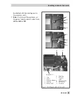
Page 83: ...ductive alarm under Code 38 from NO to YES EB 8384 4 EN 83 Retrofitting an inductive limit switch Fig 27 Retrofitting an inductive limit switch 1 Cap 2 Screws 3 Rotary pushbutton 4 Marking 5 Rotary sw...

Page 84: ...ture use inside hazardous areas must comply with the safety requirements placed on serviced devices Before being used in side hazardous areas test the devices ac cording to the specifications for serv...

Page 85: ...nsically safe circuits to check or calibrate the apparatus must only be performed with intrinsically safe current voltage calibrators and mea suring instruments to rule out any damage to components re...

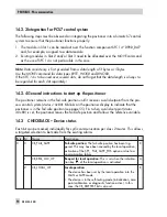
Page 86: ...tent with Profile 3 01 with the extension Condensed status and diagnostic messages V1 0 14 2 Cyclic data exchange Cyclically transmitted parameters The following parameters that are transmitted in cyc...

Page 87: ...sured value status 14 2 1 GSD files The General Station Description file GSD file is included in the scope of delivery for every PROFIBUS positioner and supplies all information required for the cycli...

Page 88: ...h Profile 3 01 are not set Additionally the DI Blocks of Type 3730 4 cannot be used as they are not available in Type 3785 When replacing the Type 3785 Positioner with the Type 3730 4 Positioner the f...

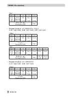
Page 89: ...hange this setting 14 2 2 Data exchange The relationship between output and input is based on the control system master class 1 SLOT 1 Version 1 Module SP 0x4A or 0x82 0x84 0x08 0x05 Output Byte 0 1 2...

Page 90: ...et 4 Fraction Octet 5 Fraction SP value Floating Point IEEE Status Input Byte 0 1 2 3 4 5 6 Octet 1 Sign Exponent Octet 2 Exponent Fraction Octet 3 Fraction Octet 4 Fraction Octet 5 Fraction Octet 1 O...

Page 91: ...3 4 5 6 7 8 9 Octet 1 Sign Exponent Octet 2 Exponent Fraction Octet 3 Fraction Octet 4 Fraction Octet 5 Fraction Octet 1 Octet 2 Octet 1 Octet 2 Octet 3 READBACK value Floating Point IEEE Status POS_...

Page 92: ...ion Octet 5 Fraction Octet 1 Sign Exponent Octet 2 Exponent Fraction Octet 3 Fraction Octet 4 Fraction Octet 5 Fraction SP value Floating Point IEEE Status RCAS_IN value Floating Point IEEE Status Inp...

Page 93: ...SLOT 2 3 4 Version 1 Module Discrete Input DI 0x91 Input Byte 0 1 Octet 1 Value Octet 2 State DI_OUT Value DI_OUT Status EB 8384 4 EN 93 PROFIBUS PA communication...

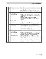
Page 94: ...stem status 0x80 S blinks on the positioner display to indicate that the positioner is in the fail safe position see page 55 First when a valid set point status 0x80 is set the positioner leaves the f...

Page 95: ...nally set values A 3 CB_SIMULATE Simulation mode active This is set when the simulation mode of at least one Function Block is active The simulation mode of the AO Function Block allows the controlled...

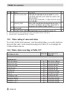
Page 96: ...4 Status coding of measured values The COND_STATUS_DIAG parameter in the Physical Block allows you to select whether the measured value status is communicated according to the Profile 3 01 or accordi...

Page 97: ...BAD_DEVICE_FAILURE Data memory 0xA4 GOOD_MAINT_REQ Test calculation 0x0C BAD_DEVICE_FAILURE Program loading error 0x0C BAD_DEVICE_FAILURE Data errors Control parameter 0xA4 GOOD_MAINT_REQ Poti paramet...

Page 98: ...er whole range 0x80 GOOD_NON_SPECIFIC Much higher over partial range 0x80 GOOD_NON_SPECIFIC Much lower over partial range 0x80 GOOD_NON_SPECIFIC Much higher over whole range TEST 0x80 GOOD_NON_SPECIFI...

Page 99: ...nce lines 0x80 GOOD_NON_SPECIFIC Zero point shift monotonously upwards average value below reference lines 0x80 GOOD_NON_SPECIFIC Zero point alternating average value below reference lines 0x80 GOOD_N...

Page 100: ...ero point error 0xA4 GOOD_MAINT_REQ DIA_ZERO_ERR Autocorrection 0x80 GOOD_NON_SPECIFIC DIA_MAINTENANCE DIA_MEM_CHECKSUM Fatal error 0x24 BAD_MAINT_ALARM DIA_HW_ELECTR Extended diagnostics available 0x...

Page 101: ...GOOD_MAINT_REQ DIA_MEM_CHECKSUM Options parameters 0xA4 GOOD_MAINT_REQ DIA_MEM_CHECKSUM Info parameter 0xA4 GOOD_MAINT_REQ DIA_MEM_CHECKSUM PA parameter 0xA4 GOOD_MAINT_REQ DIA_MEM_CHECKSUM Diagnosti...

Page 102: ...e TEST 0x80 GOOD_NON_SPECIFIC Much lower over partial range TEST 0x80 GOOD_NON_SPECIFIC Leakage pneumatics Perhaps existing TEST 0x80 GOOD_NON_SPECIFIC Perhaps existing 0x80 GOOD_NON_SPECIFIC Perhaps...

Page 103: ...age value below reference lines 0x80 GOOD_NON_SPECIFIC Connection positioner valve No opt travel transm TEST 0x80 GOOD_NON_SPECIFIC Perhaps loose 0x80 GOOD_NON_SPECIFIC Perhaps limit range 0x80 GOOD_N...

Page 104: ...ntinue afterwards with the normal data exchange The diagnostic alarm is composed of the standard diagnosis according to PROFIBUS DP and the user specific diagnosis The first six octets of the diagnost...

Page 105: ...are also included in these bytes The manufac turer specific diagnosis listed in the table below is transmitted in the eleventh byte and above The contents of both parameters of the Physical Block DIA...

Page 106: ...DIA_COLDSTART new start up cold start performed 5 DIA_MAINTENANCE maintenance required 1 6 DIA_CHARACT characteristic invalid 7 IDENT_NUMBER_VIOLATION selected ID no has not been implemented by the d...

Page 107: ...arameter see Code 68 4 Poti parameter see Code 69 5 Adjustment parameter see Code 70 6 Internal device error 1 see Code 73 7 General parameter see Code 71 18 3 0 No emergency mode see Code 76 1 Progra...

Page 108: ...Friction Higher over whole range 2 6 Friction Lower over whole range 2 7 Friction Higher over partial range 2 22 3 0 Friction Lower over partial range 2 1 Friction Higher whole range TEST 2 2 Frictio...

Page 109: ...4 Attachment between positioner and valve Perhaps loose TEST 2 5 Working range Mostly near closing position 2 6 Working range Mostly near max opening 2 7 Working range Mostly closing position 2 26 3...

Page 110: ...2 MS2 is mainly used for commissioning parameter configuration and for diagnostic purposes The Device Description can be downloaded at the SAMSON Internet site www samson de to configure parameters in...

Page 111: ...e lever in relation to the central axis is displayed in de grees 1 Manual w 0 to 100 0 of the nominal range Adjust the manual set point with the rotary pushbutton the current travel angle is displayed...

Page 112: ...0 0 200 120 0 40 0 to 200 0 90 90 0 24 0 to 110 0 5 Nominal range mm or angle ESC For initialization using NOM or SUb the nominal travel angle of rotation of the valve must be entered The permissible...

Page 113: ...x range value Code 9 Usually the operating range and the nominal range are identi cal The nominal range can be limited to the operating range by the lower and upper x range values Value is displayed...

Page 114: ...maximum tight closing of the valve Codes 14 15 have priority over Codes 8 9 10 11 Codes 21 22 have priority over Codes 14 15 15 Final position w 50 0 to 100 0 of the span adjusted via Code 12 13 OFF E...

Page 115: ...KP step influences the system deviation 18 TV step 1 2 3 4 OFF OFF ESC Displaying or changing TV see note under KP step A change of the TV step has no effect on the system deviation 19 Tolerance band...

Page 116: ...not activated when the fail safe function or solenoid valve is triggered nor upon failure of the auxiliary power 23 Total valve travel 0 to 99 107 0 Exponential reading from 9999 travel cycles onwards...

Page 117: ...supplied automatic reference variable Man mode indicates the supplied manual reference variable 43 Firmware info Control Display only indicates the positioner type and the current firmware version in...

Page 118: ...ow 20 C that has ever occurred d2 Maximum temperature 20 The highest temperature above 20 C that has ever occurred d3 Number of zero calibrations The number of zero calibrations since the last initial...

Page 119: ...e F3 Counter device start ups F4 Counter reset communication F5 Counter reset control F6 Counter reset bus connection F7 Slave status 0 Undefined 2 wait_cfg 1 wait_prm 3 data_exchg AO Function Block A...

Page 120: ...Final_Value Value Displays the output value FVR t7 AO Final_Value State and its status t8 AO Final_Position_ Value Value Displays the current valve position FVR t9 AO Final_Position_ Value State and i...

Page 121: ...Mode DI2 Required operating mode L1 Actual Mode DI2 Actual operating mode L2 DI2 Trd PV_D Value Displays the discrete input variable L3 DI2 Trd PV_D State and its status L4 DI2 Fb Target Mode Require...

Page 122: ...Recommended action Check attachment and re initialize the positioner 52 Attachment Positioner attachment incorrect Nominal travel angle Code 5 could not be achieved during initialization under NOM no...

Page 123: ...because you are required to enter the pin position for the selected initialization modes NOM and SUb Recommended action Enter pin position over Code 4 and nominal travel angle over Code 5 Re initiali...

Page 124: ...on as possible The emergency mode on the display is indicated by a blinking control symbol and 4 dashes instead of the position indication Note on the control If the measuring system has failed the po...

Page 125: ...eter error of the digital potentiometer Recommended action Confirm error perform reset and re initialize the positioner 70 Calibration Error in the production calibration data Subsequently the device...

Page 126: ...inG runs across the display If the device loads a program that does not correspond to that of the positioner the valve moves to the fail safe position It is not possible to make the valve leave this f...

Page 127: ......

Page 128: ...128 EB 8384 4 EN OS OUT SCALE OUT POSITIONING_ VALUE FEEDBACK_ VALUE INCREASE_CLOSE MOVING_DIRECTION Block Mode FINA Code 7 PV SCALE READBACK AUTO MAN LO Appendix AO Trd...

Page 129: ...INAL_VALUE_RANGE FINAL_VALUE_RANGE PRESSURE_LIMIT Actuator MOVING_DIRECTION Clear Fail Safe Set Fail Safe Code 8 9 Code 8 9 Travel sensor Code 7 Code 0 Code 20 Code 16 Code 10 11 Code 14 15 Tight clos...

Page 130: ...N 33 r Co DEVICE_ID 27 r Co DEVICE_INSTAL_DATE 38 S r w ALL Co DEVICE_MAN_ID 26 r Co DEVICE_MESSAGE 37 S r w ALL Us DEVICE_SER_NUM 28 r Co DE DIAG_EVENT_SWITCH 44 S r w ALL Co DIAGNOSIS Continued next...

Page 131: ...ains the serial number of the field device and provides clear identification of the device in combination with DEVICE_MAN_ID and DEVICE_ID Contains the classification of the diagnostic and status alar...

Page 132: ...0 1 Solenoid valve active 0 2 LV total valve travel Code 24 0 3 Control loop error Code 57 0 4 Zero point error Code 58 0 5 Autocorrection Code 59 0 6 Fatal error Code 60 0 7 Extended diagnostics avai...

Page 133: ...alibration Code 70 2 6 No production calibration 2 7 General parameters Code 71 3 0 Emergency mode No error Code 76 3 1 Program loading error Code 77 3 2 Options parameter Code 78 3 3 Info parameter C...

Page 134: ...35 S r w ALL 1 0x0001 2506 0x09CA 2712 0x0A98 32768 0x8000 32769 0x8001 32770 0x8002 Co Re No W Re No ad Re Re No Re No Identification parameters without bus address valve and actuator data Ph ID AO...

Page 135: ...CE_MESSAGE DESCRIPTOR IDENT_LIMIT_SWITCHES1 IDENT_NUMBER_SELECTOR TAG_DESC TEXT_INPUT 1 to 51 AO Function Block TAG_DESC AO Transducer Block ACTUATOR_MAN ACTUATOR_SER_NUM ADD_GEAR_ID ADD_GEAR_INST_DAT...

Page 136: ...a HW_WRITE_ PROTECTION 41 r 0 Unprotected 1 Protected Ind IDENT_NUMBER_ SELECTOR 40 S r w ALL 0 Profile specific ID 0x9710 1 Manufacturer specific ID 0x071D 2 Compatibility mode Us LOCAL_OP_ENA 39 S r...

Page 137: ...ch on the device Used to select the ID number GSD file PA139710 GSD GSD file SAMS071D GSD Local operation enabled If communication fails for a time longer than 30 seconds local operation will be enabl...

Page 138: ...s Index Parameter 16 BLOCK_OBJECT 17 ST_REV 18 TAG_DESC 19 STRATEGY 20 ALERT_KEY Index Parameter 21 TARGET_MODE 22 MODE_BLK 23 ALARM_SUM 24 SOFTWARE_REVISION 25 HARDWARE_REVISION Index Parameter 26 DE...

Page 139: ...IS_MASK 32 DIAGNOSIS_MASK_EXT 33 DEVICE_CERTIFICATION 34 WRITE_LOCKING 35 FACTORY_RESET Index Parameter 36 DESCRIPTOR 37 DEVICE_MESSAGE 38 DEVICE_INSTAL_DATE 39 LOCAL_OP_ENA 40 IDENT_NUMBER_ SELECTOR...

Page 140: ...d valve CB_FAIL_SAFE DI2 4 Actively open Diagnosis leakage sensor CD_ADD_INPUT Solenoid valve DI2 5 Actively closed Diagnosis leakage sensor CD_ADD_INPUT Solenoid valve DI2 6 Actively open Diagnosis l...

Page 141: ...ly open This information is also transmitted cyclically with CHECKBACK CB_ADD_INPUT Additionally the state of the internal solenoid valve is switched to Function Block DI2 A leakage sensor is operated...

Page 142: ...aps stiffness increased TEST 0 1 At full capacity 0 2 At full capacity TEST Shift of working range 0 3 Closed position 0 4 Max open Friction 0 5 Higher over whole range 0 6 Lower over whole range 0 7...

Page 143: ...s aver age above reference lines 3 4 Shift monotonously upwards average above reference lines 3 5 Alternating average above ref lines 3 6 Shift monotonously downwards aver age below reference lines 3...

Page 144: ...STELLUNG 77 r Element Parameter name St 0 MESSWERT_0 29 MESSWERT_29 30 REFERENZWERT FEATURE_SELECT 64 S r w ALL Bit 0 false 1 true C Byte Bit 0 0 BAD_DEVICE_FAILURE sets DIAG_EXT bit By pr al C p 0 1...

Page 145: ...llowing errors is detected by the positioner Test calculation fatal error program loading error no production calibration hardware i p converter The activation of this function allows errors to be sim...

Page 146: ...meter name St 0 X_INTERVAL_VALUE_0 21 X_INTERVAL_VALUE_21 22 X_AVERAGE 23 NUMBER_MESS_POINTS 0 21 22 23 HISTOGRAMM_Z_KURZ 71 r Element Parameter name St 0 Z_INTERVAL_VALUE_0 12 Z_INTERVAL_VALUE_12 13...

Page 147: ...al 21 22 Average value x for short term Statistical information AUTO Structure for long term histogram plotting x 0 Valve position interval 0 21 Valve position interval 21 22 Average value x for long...

Page 148: ...talled 3 Inductive limit switch installed 4 to 8 Options 4 to 8 installed D PRODUCTION_ID 57 S r w ALL READING_DIRECTION 58 S r w ALL Th SPRUNGANTWORT_E_1 to SPRUNGANTWORT_E_4 103 to 106 r r Te to Te...

Page 149: ...ts MAN Step response Setpoint deviation data set 1 to Tests MAN Step response Setpoint deviation data set 4 Tests MAN Step response Drive signal data set 1 Tests MAN Step response Drive signal data se...

Page 150: ...STEMPEL 1 TESTINFO 2 FORTSCHRITT 3 REFERENZWERT_0 4 WIEDERHOLUNGSWERT_0 51 REFERENZWERT_24 52 WIEDERHOLUNGSWERT_24 STATIONAER_KURZ 73 r Element Parameter name St 0 MITTELWERT_0 21 MITTELWERT_21 STATIO...

Page 151: ...ce and repetition values Statistical information AUTO Structure for drive signal diagram in steady state in short term monitoring Statistical information AUTO Structure for drive signal diagram in ste...

Page 152: ...IAGNOSIS_EXT_2_RAW 64 FEATURE_SELECT 65 TEST_FUNCTION 66 HISTOGRAMM_X_LANG 67 HISTOGRAMM_E_LANG 68 HISTOGRAMM_Z_LANG 69 HISTOGRAMM_X_KURZ 70 HISTOGRAMM_E_KURZ 71 HISTOGRAMM_Z_KURZ 72 STATIONAER_LANG 7...

Page 153: ...RUNGANTWORT_E_1 104 SPRUNGANTWORT_E_2 105 SPRUNGANTWORT_E_3 Index Parameter 106 SPRUNGANTWORT_E_4 107 SPRUNGANTWORT_ ZEIT_1 108 SPRUNGANTWORT_ ZEIT_2 109 SPRUNGANTWORT_ ZEIT_3 110 SPRUNGANTWORT_ ZEIT_...

Page 154: ...H 24 S r w ALL Co BLOCK_OBJECT 16 r CHECK_BACK 37 r De CHECK_BACK_MASK 38 r Bit 0 Status not supported Bit 1 Status supported De FSAFE_TIME 31 S r w ALL Tim Th FSAFE_TYPE 32 S r w ALL De 0 1 2 FSAFE_V...

Page 155: ...nt is saved Actuator moves to the fail safe position defined by the actuator springs Default value for setpoint reference variable w used when a communication failure or start up is detected The assig...

Page 156: ...w ALL Ra RCAS_IN 28 S r w ALL Range defined in PV_SCALE Se Pr RCAS_OUT 34 r Range defined in PV_SCALE Se Pr READBACK 27 r Range defined in PV_SCALE Cu SETP_DEVIATION 36 r Se SIMULATE 39 S r w ALL Si...

Page 157: ...rent position with status Controlled variable x in relation to travel range angle of rotation OUT_SCALE Setpoint deviation Simulation Simulation of a value status for READBACK Setpoint with status Set...

Page 158: ...CT 17 ST_REV 18 TAG_DESC 19 STRATEGY 20 ALERT_KEY Index Parameter 21 TARGET_MODE 22 MODE_BLK 23 ALARM_SUM 24 BATCH 25 SP Index Parameter 26 PV_SCALE 27 READBACK 28 RCAS_IN 29 IN_CHANNEL 30 OUT_CHANNEL...

Page 159: ...YPE 33 FSAFE_VALUE 34 RCAS_OUT 35 POS_D Index Parameter 36 SETP_DEVIATION 37 CHECK_BACK 38 CHECK_BACK_MASK 39 SIMULATE 40 INCREASE_CLOSE Index Parameter 41 OUT 42 OUT_SCALE 240 VIEW1 Description Defin...

Page 160: ...position 2 Closing towards 0 position 3 None saving position remains kept Se du ACTUATOR_MAN 140 S r w ALL Ac ACTUATOR_SER_NUM 145 S r w ALL Sp ACTUATOR_TYPE 142 r 0 Electropneumatic 1 Electric 2 Elec...

Page 161: ...tuator and valve needs to move through the rated travel range angle of rotation to open the valve measured during initialization Sets the fail safe action to be performed by the actuator in case of a...

Page 162: ...plug valve eq percent Ty MODE_BLK 86 r M POSITIONING_VALUE 137 r Unit of the OUT_SCALE Ind RATED_TRAVEL 112 S r w ALL 15 0 mm Sp SELF_CALIB_CMD 113 S r w ALL Co 0 No test normal operation 1 2 Start in...

Page 163: ...No function 40 Reset x signal 41 Reset i p converter 42 Reset Hardware 43 Reset Control parameter 44 Reset Poti parameter 45 Reset Calibration 46 Reset General parameters 47 Reset Internal device err...

Page 164: ...d up 11 12 13 14 15 16 17 SERVO_GAIN_1 115 S r w ALL 7 K SERVO_RATE_1 116 S r w ALL 2 T SETP_CUTOFF_DEC 118 S r w ALL 0 0 Fin If t to Ele SETP_CUTOFF_INC 119 S r w ALL 125 0 Fin If t to Ele ST_REV 81...

Page 165: ...iable exceeds the entered value the valve moves towards the final position which corresponds to 0 reference variable Electropneumatic actuators are completely filled with air or vented depending on th...

Page 166: ..._DATE 105 LIN_TYPE 112 RATED_TRAVEL Index Parameter 113 SELF_CALIB_CMD 114 SELF_CALIB_STATUS 115 SERVO_GAIN_1 116 SERVO_RATE_1 118 SETP_CUTOFF_DEC 119 SETP_CUTOFF_INC 125 TOTAL_VALVE_TRAVEL Ind 12 12...

Page 167: ...M 147 ADD_GEAR_MAN 148 ADD_GEAR_ID 149 ADD_GEAR_INST_DATE 241 VIEW1 Description Required transit time CLOSED s Minimum time required to move through the working range to 0 position Required transit ti...

Page 168: ...Ind CHARACT_TYPE 173 S r w ALL Ty Te CLOSING_DIRECTION 165 S r w ALL Ind COUNTER_INIT_START 198 r Sp DATALOGGER 185 r Element Parameter name Str 0 DATALOGGER_SELECT 1 TRIGGER_SELECT 2 SAMPLE_RATE 3 ST...

Page 169: ...have been performed since the last reset Structure of read and write parameters of the data logger EXPERT Structure of read parameters of the data logger EXPERT 0 Test information 1 Max pretrigger tim...

Page 170: ...RESSURE_BALANCING 10 FLOW_CHARACTERISTC 11 FLOW_DIRECTION 12 NOM_DIAMETER 13 NOM_DIAMETER_DN 14 KVS_UNIT 15 KVS_VALUE 16 SEAT_DIAM_VALVE DEVICE_INIT_STATE 163 r Ind DIAG_TESTINFO 201 r Inf 0 No active...

Page 171: ...coefficient 16 Seat diameter of the valve Indicates whether the device has been initialized Info parameter concerning an active diagnostic test running EXPERT 8 d4 Step response test 16 d5 Hysteresis...

Page 172: ...signal test in steady state 11 Start drive signal test in hysteresis 12 Stop drive signal test in hysteresis 13 Start static characteristic test 14 Stop static characteristic test 15 Start reference t...

Page 173: ...monitoring 32 Reset Drive signal diagram hysteresis short term monitoring 33 Reset y x reference values 34 Reset Reference measurement hysteresis 35 Reset Data logger 36 Reset Static characteristic 3...

Page 174: ...r Ind PIN_POSITION 160 S r w ALL Th Th Ta PRESSURE_LIMIT 177 S r w ALL 1 Off 2 3 7 bar 3 2 4 bar 4 1 4 bar Us SELF_CALIB_WARNING 167 r 0 Inf SET_FAIL_SAFE_POS 178 S r w ALL 0 Not active 1 Set fail saf...

Page 175: ...lows the valve to be moved to its actual fail safe position over the bus The positioner remains however still in AUTO mode Fail safe position is indicated by an S blinking on the display Note An S bli...

Page 176: ...G 8 STEP_PROGRESS 9 RISE_TIME_FALLING 10 SETTLING_TIME_FALLING 11 RISE_TIME_RISING 12 SETTLING_TIME_RISING 13 DURATION_OF_TEST 14 TESTINFO STEP_RESPONSE_RW 189 S r w ALL Element Parameter name Str 0 S...

Page 177: ...1 Step end 2 Scan rate 3 Ramp time rising 5 Ramp time falling 6 Delay time after step 7 Number of steps Indicates whether an initialization has been performed in SUb mode Structure containing paramet...

Page 178: ...169 S r w ALL En USER_CHARACT 203 S r w ALL Element Parameter name Us 0 X_0 1 Y_0 20 X_10 21 Y_10 ZERO_POINT_LIMIT 197 S r w ALL Ind Index Parameter 160 PIN_POSITION 161 INIT_METHOD 162 SUB_MODE_INIT...

Page 179: ...L_VALUE 185 DATALOGGER 186 DATALOGGER_READ 187 TEMP_MONITORING 188 STEP_RESPONSE_R 189 STEP_RESPONSE_RW 190 EVENT_LOGGING_1 191 EVENT_LOGGING_2 Index Parameter 192 ENHANCED_DIAG_CMD 193 ELAPSED_HOURS_...

Page 180: ...LERT_KEY 20 S r w ALL 0 Co BATCH 24 S r w ALL Co BLOCK_OBJECT 16 r CHANNEL 30 S r w ALL DI1 0 Not active 780 Active DI2 0 Not active 524 Active Lin FSAFE_TYPE 36 S r w ALL 0 Status UNCERTAIN substitut...

Page 181: ..._D when the sensor or the sensor electronics error is detected Inverts the input value PV_D sent by DI Transducer Block before it is saved in the OUT_D parameter and sent Indicates the actual mode Thi...

Page 182: ...w ALL M SENSOR_SER_NUM 70 S r w ALL Se SENSOR_WIRE_CHECK 68 S r w ALL Detection of 0 Lead breakage and short circuit enabled 1 Lead breakage enabled short circuit disabled 2 Lead breakage disabled sh...

Page 183: ...are available to the Function Block Identification of the sensor type Manufacturer of the sensor Serial number of the sensor d d Enables the lead breakage and short circuit detection Collective comman...

Page 184: ...28 14 80 164 Output 38 Supply 9 86 70 15 46 34 70 70 28 Schild 58 58 Fig 29a NAMUR and direct attachment Direct attachment Attachment acc to IEC 60534 6 Lever mm S 17 M 50 L 100 XL 200 Pressure gauge...

Page 185: ...4 EN 185 Dimensions in mm 62 164 3 8 200 164 164 13 62 24 Fig 29b Attachment according to VDI VDE 3847 Attachment according to VDI VDE 3847 onto Type 3277 Attachment according to VDI VDE 3847 onto NA...

Page 186: ...10 fixing level 1 size AA1 to AA4 A1 Z A2 Output A1 Output A2 Supply 9 50 80 58 130 49 59 79 76 50 150 Light version Reversing amplifier optional Reversing amplifier Type 3710 see drawing of heavy dut...

Page 187: ...2 bracket surface Level 1 actuator surface Actuator Dimensions in mm Size A B C d Mmin D AA0 50 25 15 5 5 for M5 66 50 AA1 80 30 20 5 5 for M5 96 50 AA2 80 30 30 5 5 for M5 96 50 AA3 130 30 30 5 5 fo...

Page 188: ...188 EB 8384 4 EN...

Page 189: ...EB 8384 4 EN 189...

Page 190: ...190 EB 8384 4 EN...

Page 191: ...EB 8384 4 EN 191...

Page 192: ...192 EB 8384 4 EN...

Page 193: ...EB 8384 4 EN 193...

Page 194: ...194 EB 8384 4 EN...

Page 195: ...EB 8384 4 EN 195...

Page 196: ...196 EB 8384 4 EN...

Page 197: ...EB 8384 4 EN 197...

Page 198: ...198 EB 8384 4 EN...

Page 199: ...EB 8384 4 EN 199...

Page 200: ...might already be integrated in the associated apparatus The number of passive devices connected to the bus segment is not limited due to I S reasons If the above rules are respected the inductance an...

Page 201: ...nect to Terminal 81 Voc 28V max and Rmin 245 Return channel connect to Terminal 82 28V max with diodes Return zero current Circuit 4 can be connected to a CSA Certified zener barrier that is rated as...

Page 202: ...ntrol Relay KHA5 OTI Ex2 KHA6 OTI Ex1 or KHA6 OTI Ex2 with Model SJ b N Proximity Sensors System parameters Control Relay Terminal No Groups L mH C F V0C V ISC mA Vmax V Rmin A B 192 2 66 C E 671 7 9...

Page 203: ...associated apparatus The number of passive devices connected to the bus segment is not limited due to I S reasons If the above rules are respected the inductance and capacitance of the cable will not...

Page 204: ...installation must be in accordance with the National Electrical Code ANSI NFPA 70 and ANSI ISA RP 12 06 01 3 Cable entry M 20 x1 5 or metal conduit acc to dwg No 1050 0540 Addendum Page 10 Revisions...

Page 205: ...al No Groups L mH C F V0C V ISC mA Vmax V Rmin A B 192 2 66 C E 671 7 9 1 3 2 3 4 6 5 6 D F G 1000 21 3 10 5 13 10 5 811 HAZARDOUS LOCATION SAFE LOCATION Ex nA II T6 Ex nL IIC T6 Zone 2 Class I II Div...

Page 206: ...206 EB 8384 4 EN...

Page 207: ...EB 8384 4 EN 207...

Page 208: ...208 EB 8384 4 EN...

Page 209: ...EB 8384 4 EN 209...

Page 210: ...210 EB 8384 4 EN...

Page 211: ...EB 8384 4 EN 211...

Page 212: ...SAMSON AG MESS UND REGELTECHNIK Weism llerstra e 3 60314 Frankfurt am Main Germany Phone 49 69 4009 0 Fax 49 69 4009 1507 Internet http www samson de EB 8384 4 EN S Z 2017 07...

Reviews: