background image

11-2  

EB 3756 EN

Summary of Contents for 3756

Page 1: ...Translation of original instructions EB 3756 EN Edition April 2023 Type 3756 Booster Valve...

Page 2: ...If you have any questions about these instructions contact SAMSON s After sales Service aftersalesservice samsongroup com Documents relating to the device such as the mounting and operating instructi...

Page 3: ...red goods 4 1 4 2 Removing the packaging from the booster valve 4 1 4 3 Transporting the booster valve 4 1 4 4 Storing the booster valve 4 1 5 Installation 5 1 5 1 Installation conditions 5 1 5 2 Prep...

Page 4: ...Contents EB 3756 EN 10 Decommissioning 10 1 11 Removal 11 1 12 Repairs 12 1 12 1 Returning devices to SAMSON 12 1 13 Disposal 13 1 14 Certificates 14 1 15 Annex 15 1 15 1 After sales service 15 1...

Page 5: ...lowing applications Use outside the limits defined during sizing and by the technical data Furthermore the following activities do not comply with the intended use Use of non original spare parts Perf...

Page 6: ...Responsibilities of the operator Operators are responsible for proper use and compliance with the safety regulations Operators are obliged to provide these mounting and operating instructions to the...

Page 7: ...rs if inserted into the valve Do not touch any moving valve parts while the control valve is in operation Before performing any mounting or installation work on the booster valve put the control valve...

Page 8: ...4 Warnings on the device Warning Meaning of the warning Warning against sudden loud noise The booster valve mounted onto the control valve can cause the pneumatic actuator to vent A loud noise may oc...

Page 9: ...ngs on the device 2 Markings on the device 2 1 Nameplate SAMSON 3756 Booster Valve Made in Germany Model 3756 Var ID Serial no 2 3 4 5 1 1 Article code 2 Device index 3 Safety approval 4 Configuration...

Page 10: ...return mechanism 1 5 2 way function with two detent positions 2 5 3 way function with spring centered mid position ports 2 and 4 closed 3 5 3 way function with spring centered mid position ports 2 and...

Page 11: ...eries connection 1oo2 redundancy 5 9 0 0 1 0 Emergency air supply parallel connection 2oo2 redundancy 5 9 0 0 1 1 1 The air flow rate when p1 2 4 bar and p2 1 0 bar is calculated using the following f...

Page 12: ...2 4 EB 3756 EN...

Page 13: ...ition after the control pres sure is removed Function of the spool The booster valve consists of a body with a spool actuated on one side with return spring In the neutral position the connection from...

Page 14: ...3 or at least 10 K below the lowest ambient temperature to be expected Actuation control pressure switching points Pneumatic connection G 1 8 or 1 8 NPT 1 4 to 10 bar 0 2 bar switchover to neutral po...

Page 15: ...ISO 8573 1 Max particle size and density Class 4 Oil content Class 3 Pressure dew point Class 3 or at least 10 K below the lowest ambient temperature to be expected Actuation control pressure switchin...

Page 16: ...573 1 Max particle size and density Class 4 Oil content Class 3 Pressure dew point Class 3 or at least 10 K below the lowest ambient temperature to be expected Actuation control pressure switching poi...

Page 17: ...corrosive substances or nitrogen air containing oil or non corrosive gases Compressed air quality acc to ISO 8573 1 Max particle size and density Class 4 Oil content Class 3 Pressure dew point Class 3...

Page 18: ...corrosive gases Compressed air quality acc to ISO 8573 1 Max particle size and density Class 4 Oil content Class 3 Pressure dew point Class 3 or at least 10 K below the lowest ambient temperature to b...

Page 19: ...ntent Class 3 Pressure dew point Class 3 or at least 10 K below the lowest ambient temperature to be expected Actuation control pressure switching points CNOMO interface 1 4 to 10 bar 3 Type 3963 Sole...

Page 20: ...Class 3 Pressure dew point Class 3 or at least 10 K below the lowest ambient temperature to be expected Actuation control pressure switching points CNOMO interface 1 4 to 10 bar 3 Type 3963 Solenoid...

Page 21: ...re to be expected Actuation control pressure switching points Pneumatic connection G or NPT 1 4 to 3 bar 0 2 bar switchover to neutral position 1 4 bar switchover to operating position CNOMO interface...

Page 22: ...corrosive substances or nitrogen air containing oil or non corrosive gases Compressed air quality acc to ISO 8573 1 Max particle size and density Class 4 Oil content Class 3 Pressure dew point Class 3...

Page 23: ...IL Details in Safety Manual u SH 3756 T V Contents Mounted on control valves according to DIN 3394 1 DIN EN 161 DIN 32725 DIN EN 264 and DIN 32730 Number S 284 2013 E2 rev 01 Date 2014 01 16 3 2 Dimen...

Page 24: ...3 12 EB 3756 EN...

Page 25: ...following sequence Do not remove the packaging until im mediately before installation of the booster valve Dispose and recycle the packaging in accordance with the local regulations 4 3 Transporting...

Page 26: ...o not damage the corrosion protection coating Protect the booster valve against moisture and dirt In damp spaces prevent con densation If necessary use a drying agent or heating Observe storage temper...

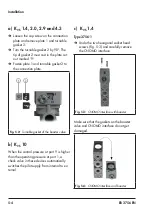
Page 27: ...alve in such a way that the vent ports face downward in cases where this is not possible mount them in the horizontal position 5 2 Preparation for installation Before installation make sure the follow...

Page 28: ...d screw Fig 5 1 NAMUR interface 5 4 Pneumatic connection The air connections are designed as thread ed holes with G 1 8 1 8 NPT G NPT G NPT or G 1 1 NPT threads de pending on the device version Run an...

Page 29: ...ze for lines longer than 2 m Port 8 9 12 14 4 1 Pipe 1 6x1 mm 12x1 mm Hose 2 4x1 mm 9x3 mm 1 Outside diameter x Wall thickness 2 Inside diameter x Wall thickness 5 4 2 Compressed air quality Compresse...

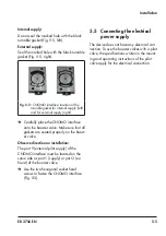
Page 30: ...Turnable gasket of the booster valve b KVS 10 When the control pressure at port 9 is higher than the operating pressure at port 1 a check valve in these devices automatically switches the pilot suppl...

Page 31: ...t all gaskets are seated properly on the boost er valve Observe direction on installation The port 9 external pilot supply of the CNOMO interface must be located on the same side as port 1 supply or p...

Page 32: ...MUR interface on NAMUR rib thread ed connection NPT 1400 9601 Adapter plate paint coated aluminum for NAMUR interface on NAMUR rib threaded connection G 1402 0827 Adapter plate paint coated aluminum f...

Page 33: ...rts while the control valve is in operation Before performing any mounting or installation work on the booster valve put the control valve out of operation by disconnecting the supply air and control...

Page 34: ...6 2 EB 3756 EN...

Page 35: ...lve is in operation Before performing any mounting or installation work on the booster valve put the control valve out of operation by disconnecting the supply air and control signal Protect it agains...

Page 36: ...7 2 EB 3756 EN...

Page 37: ...not touch any moving valve parts while the control valve is in operation Before performing any mounting or installation work on the booster valve put the control valve out of operation by disconnecti...

Page 38: ...8 2 EB 3756 EN...

Page 39: ...e Do not touch any moving valve parts while the control valve is in operation Before performing any mounting or installation work on the booster valve put the control valve out of operation by disconn...

Page 40: ...lates on the booster valve for their readability and com pleteness Contact SAMSON when nameplates or labels are damaged missing or incorrect to renew them Clean any inscriptions that are covered with...

Page 41: ...nal reconnec tion Crush hazard arising from moving parts on the valve Control valves contain moving parts actua tor and plug stem which can injure hands or fingers if inserted into the valve Do not to...

Page 42: ...10 2 EB 3756 EN...

Page 43: ...uch any moving valve parts while the control valve is in operation Before performing any mounting or installation work on the booster valve put the control valve out of operation by disconnecting the...

Page 44: ...11 2 EB 3756 EN...

Page 45: ...vice for repair work 12 1 Returning devices to SAMSON Defective booster valves can be returned to SAMSON for repair Proceed as follows to return devices to SAMSON 1 Put the booster valve out of operat...

Page 46: ...12 2 EB 3756 EN...

Page 47: ...g national registers national registers WEEE reg no DE 62194439 FR 02566 Observe local national and internation al refuse regulations Do not dispose of components lubricants and hazardous substances t...

Page 48: ...13 2 EB 3756 EN...

Page 49: ...shown were up to date at the time of publishing The latest certificates can be found on our website u www samsongroup com Products Applications Product selector Valve accessories Type 3756 SIL The SI...

Page 50: ...14 2 EB 3756 EN...

Page 51: ...EB 3756 EN 14 3...

Page 52: ...14 4 EB 3756 EN...

Page 53: ...aftersalesservice samsongroup com Addresses of SAMSON AG and its subsid iaries The addresses of SAMSON AG its subsid iaries representatives and service facilities worldwide can be found on our websit...

Page 54: ...15 2 EB 3756 EN...

Page 55: ......

Page 56: ...2023 04 05 English SAMSON AKTIENGESELLSCHAFT Weism llerstra e 3 60314 Frankfurt am Main Germany Phone 49 69 4009 0 Fax 49 69 4009 1507 samson samsongroup com www samsongroup com EB 3756 EN...

Reviews: