EB 8355-2 EN
5-21
Installation
Check the positioning speed by pushing
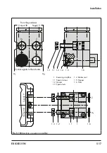
the diaphragm lever (3 in
it will go.
2. Adjust the set point at the input to ap-
prox. 50 % of its range. Then turn the ze
-
ro adjuster (6.2 in
) until the
valve is at approximately 50 % valve
travel.
3. Use the adjuster (8 in
proportional band X
p
to a value half way
(half turn).
4. Check the valve's tendency to hunt and
the positioning speed by briefly tapping
the diaphragm lever (3 in
). The
Xp value is to be adjusted to be as small
as possible, without considerable over-
shooting occurring.
Additional points that apply concerning ad
-
justment:
Î
Always adjust the Xp restriction before
setting the starting point.
Î
In case of a zero shift (e.g. due to a sub
-
sequent change in the restriction setting
or supply pressure), check the zero set
-
ting and readjust it.
−
When the positioner is controlled by a
computer whose signal is limited, e.g.
between 4 to 20 mA, set the positioner
to the range from 4.5 to 20 mA. This is
the only way to ensure that the actuator
is completely vented and the valve com-
pletely closed when the controller issues
a 4 mA signal. For operating direction
<>, set the range to 4 to 19.5 mA.
5.5.2
Zero and span
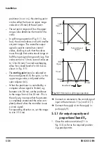
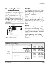
When setting the zero adjuster (6.2 in
), check whether the actuator is re
-
lieved of pressure. When the input signal is
4 mA and the operating direction >> or the
input signal is 20 mA and the operating di
-
rection <>, the pressure gauge must indicate
0 bar.
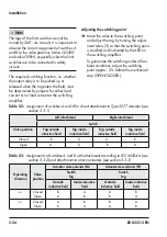
a) Actuator with "stem extends"
fail-safe action
To ensure that the total closing force of the
actuator acts on the valve, proceed as fol-
lows while adjusting the set point:
Î
With operating direction increasing/in
-
creasing <<: adjust starting point to
4.5 mA (slightly raised).
Î
With operating direction increasing/de
-
creasing <>: adjust starting point to
19.5 mA (slightly lowered).
Starting point (zero) e.g. 4 mA
1.
Turn the zero adjuster (6.2 in Fig. 5-3
)
until the valve just starts to move from its
initial position.
2.
Reduce the input signal to 0 mA and
slowly increase it again. Check whether
the valve starts to move at exactly
4.5 mA.
Correct any deviation at the zero adjust
-
).
Note
Summary of Contents for 3767
Page 10: ...1 6 EB 8355 2 EN...
Page 14: ...2 4 EB 8355 2 EN...
Page 58: ...6 2 EB 8355 2 EN...
Page 60: ...7 2 EB 8355 2 EN...
Page 70: ...10 2 EB 8355 2 EN...
Page 72: ...11 2 EB 8355 2 EN...
Page 74: ...12 2 EB 8355 2 EN...
Page 76: ...13 2 EB 8355 2 EN...
Page 78: ...14 2 EB 8355 2 EN...
Page 79: ...EB 8355 2 EN 14 3...
Page 80: ...14 4 EB 8355 2 EN...
Page 81: ...EB 8355 2 EN 14 5...
Page 88: ...14 12 EB 8355 2 EN...
Page 89: ...EB 8355 2 EN 14 13...
Page 90: ...14 14 EB 8355 2 EN...
Page 91: ...EB 8355 2 EN 14 15...
Page 92: ...14 16 EB 8355 2 EN...
Page 93: ...EB 8355 2 EN 14 17...
Page 94: ...14 18 EB 8355 2 EN...
Page 95: ...EB 8355 2 EN 14 19...
Page 96: ...14 20 EB 8355 2 EN...
Page 97: ...EB 8355 2 EN 14 21...
Page 98: ...14 22 EB 8355 2 EN...
Page 99: ...EB 8355 2 EN 14 23...
Page 100: ...14 24 EB 8355 2 EN...
Page 101: ...EB 8355 2 EN 14 25...
Page 102: ...14 26 EB 8355 2 EN...
Page 103: ...EB 8355 2 EN 14 27...
Page 104: ...14 28 EB 8355 2 EN...
Page 109: ......
Page 110: ...2 EB 8355 2 EN...
Page 111: ...EB 8355 2 EN 3...

