EB 3131 EN
27
Mounting and start-up
For exact adjustment, verify adjusted value
with a heat or flow meter.
7. Secure restriction setting using the lock
nut (16) at the set point screw (17).
Screw cap (18) back on.
8.
Lead-seal the set point setting at set point
screw (17) and cap (18).
The set point can be directly adjusted in the
version with manual adjuster. One scale divi-
sion corresponds to one turn of the set point
screw.
Tip
Note
6 Operation
6.1
Adjusting the set points
6.1.1
Flow control
Î
Type 46-7 and Type 47-1:
Adjust the
maximum differential pressure at the reg-
ulator (see section 6.1.2).
Î
Completely open the control and shut-off
valves or a bypass valve in the plant.
1. To fully load the set point spring (8) and
manual adjuster (19), turn the set point
adjuster (10) clockwise (
) as far as it
will go.
2. Unscrew the cap (18).
3. Undo the lock nut (16).
4.
Use a suitable tool (Allen key, SW 4) to
turn the set point screw (17) clockwise
(
) as far as it will go to close the re-
striction (1.2).
5.
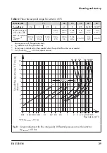
Refer to Fig. 8 to find out how many
turns are required to set the flow rate.
6.
Use a suitable tool (Allen key, SW 4) to
turn the set point screw (17) by the re-
quired number of turns. Turn it counter-
clockwise (
) to open the restriction. The
flow rate rises.
5. Check the strainer (e.g. measure the
pressure drop) and clean it, if necessary.


