14
EB 8365 EN
Attachment to the valve
3
Attachment to the valve
The accessories listed in section 2.4 are re-
quired for attachment.
Î
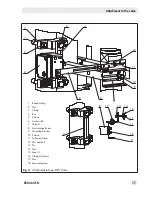
The lever (I or II) must be installed before
the limit switch is attached to the control
valve. To do so, slide the lever clamping
plate (1.1) over the lever (1) and slip
them onto the shaft (2). Tighten the fas-
tening screw (1.2).
3.1
Attachment to valve with
cast yoke
1. Attach the plate (10) to the valve's stem
connector using two screws (10.1).
2. Attach the pin (11) to the plate (10) us-
ing two nuts (11.1).
3. Unscrew the cover of the limit switch. At-
tach the limit switch to the valve yoke us-
ing the mounting screw (12), washer
(13) and O-ring (14).
Make sure that the pin (11) is inserted
through the wire strap (1.3) of the lever
(1).
3.2
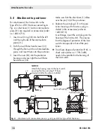
Attachment to valve with
rod-type yoke
1. Attach the plate (10) to the valve's stem
connector using two screws (10.1).
2. Attach the pin (11) to the plate (10) us-
ing two nuts (11.1).
3. Fasten the support (15) and the rod
clamping plate (16) loosely to the rod.
In the valve travel mid-position, move the
support until the center of the plate (10)
and the support (15) are aligned.
4. Fasten the rod clamping plate.
5. Attach the limit switch to the support us-
ing the mounting screw (12), washer
(13) and O-ring (14). Make sure that the
pin (11) is inserted through the wire
strap (1.3) of the lever (1).
Î
After attaching the limit switch, make
sure that the vent plug of the housing
cover faces downward when the valve is
installed
Summary of Contents for 4746
Page 4: ......
Page 27: ...EB 8365 EN 27...
Page 28: ...28 EB 8365 EN...
Page 29: ...EB 8365 EN 29...
Page 30: ...30 EB 8365 EN...
Page 31: ...EB 8365 EN 31...
Page 32: ...32 EB 8365 EN...
Page 33: ...EB 8365 EN 33...
Page 36: ...36 EB 8365 EN...
Page 37: ...EB 8365 EN 37...
Page 38: ...38 EB 8365 EN...
Page 39: ...EB 8365 EN 39...


