22
EB 8365 EN
Operation
5
Operation
5.1
Adjusting the switching
point
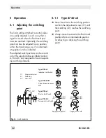
The limit switches attached to control valves
are usually adjusted in such a way that a
signal is issued when the final travel posi
-
tions are reached. Optionally, the switching
point can also be adjusted to any position
within the travel range, e.g. if an intermedi-
ate position is to be indicated.
The adjusted switch positions can be record-
ed on the supplied adhesive labels marked
A, B and C, and assigned to the correspond-
ing switching elements.
3.1
4.1, 4.2
42
(52)
42
(52)
41(51)
43(53)
41(51)
43(53)
A
A
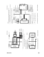
3.1 Adjustment screw
4.1 Metal tag
4.2 Cam disk
Type 4746-x2
Inductive Limit Switch
Type 4746-0281
Close three-wire sensor
PNP
Type 4746-x3
Electric Limit Switch
Type 4746-04
Pneumatic Limit Switch
Open
Supply air applied
Open
Closed
Supply air cut off
Closed
Fig. 6:
Limit contacts
5.1.1
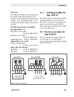
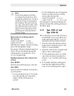
Type 4746-x2
Î
Move the valve to the switching position
and turn the adjustment screw (3.1) until
the metal tag (4.1) reaches the switching
point.
Î
Always move the valve to the final travel
positions from an intermediate position
on adjusting or checking the switching
point!
Summary of Contents for 4746
Page 4: ......
Page 27: ...EB 8365 EN 27...
Page 28: ...28 EB 8365 EN...
Page 29: ...EB 8365 EN 29...
Page 30: ...30 EB 8365 EN...
Page 31: ...EB 8365 EN 31...
Page 32: ...32 EB 8365 EN...
Page 33: ...EB 8365 EN 33...
Page 36: ...36 EB 8365 EN...
Page 37: ...EB 8365 EN 37...
Page 38: ...38 EB 8365 EN...
Page 39: ...EB 8365 EN 39...


