background image

EB 8365 EN 

 23 

Operation

Note:

The switching elements and the le-

vers required to activate them react 
to temperature fluctuations. To ensure 

reliable switching, the switching hys-
teresis between the mechanical stop 

(e.g. plug in the seat) and the switch

-

ing point of the limit switch must be 
larger than the displacement of the 
switching point caused by the tem-

perature change.

Distance between switching points for 

100 mm lever:

Contact SC3,5-N0-YE   ≥ 2 mm,
Contact SJ3,5-SN 

  ≥ 0.75 mm.

With other lever lengths, adjust the switching 
point to the changed lever length.
For example, if the lever length changes from 

100 to 160 mm, the distance between the 

switching points is increased from 2.0 to 

3.2 mm correspondingly.

Simplified adjustment of the inductive limit 

switches:
Valve CLOSED:

Close the valve until the plug sits in the seat.

Valve OPEN:

Move the valve to the desired travel position, 

e.g. final position.


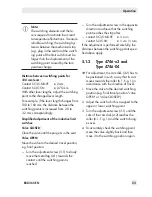
Turn the adjustment screw (3.1) to slowly 
move the metal tag (4.1) towards the 
contact until the switching point is 
reached.


Turn the adjustment screw in the opposite 
direction to achieve that the switching 
point reaches the stop after


contact SC3,5-N0-YE  ≥ 

1

/

6

 turn

contact SJ3,5-SN   

≥ 

1

/

16

 to 

1

/

10 

turn

If the adjustment is performed carefully, the 
distances between the switching points speci-

fied above apply.

5.1.2 

Type 4746-x3 and 

Type 4746-04


Î

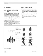
For adjustment, the cam disk (4.2) has to 
be positioned in such a way that its cam 
moves towards the roller (6.1, Fig. 1) in 
accordance with the direction of travel.

1.  Move the valve to the desired switching 

position (e.g. final travel position "valve 
OPEN" or "valve CLOSED").

2.  Adjust the switch which is assigned to the 

upper or lower switching point.

3.  Turn the adjustment screw (3.1) until the 

cam of the cam disk (4.2) reaches the 
roller (6.1, Fig. 1) and the switch chang-
es over.

4.  To accurately check the switching point, 

move the valve slightly back and then 
move it to the switching position again.

Summary of Contents for 4746

Page 1: ...Mounting and Operating Instructions EB 8365 EN Edition October 2013 Type 4746 Electric or Pneumatic Limit Switch...

Page 2: ...ng for handling SAMSON devices For the safe and proper use of these instructions read them carefully and keep them for later reference If you have any questions about these instructions contact SAMSON...

Page 3: ...approvals 12 3 Attachment to the valve 14 3 1 Attachment to valve with cast yoke 14 3 2 Attachment to valve with rod type yoke 14 3 3 Attachment to Type 3591 Valve 16 3 4 Attachment to positioner 18...

Page 4: ......

Page 5: ...device are to be operated only by personnel who has undergone special training or instructions or who is authorized to work on explosion pro tected devices in hazardous areas Refer to section 6 Any h...

Page 6: ...rs must be integrated into the output cir cuit The switching function and switching point are continuously adjustable using the adjust ment screw 3 1 2 1 2 Type 4746 x3 Electric Limit Switch In this v...

Page 7: ...limit switch Pneumatic limit switch with switching function 1 Lever for valve travel 1 1 Pin 2 Shaft 3 Switch case 3 1 Adjustment screw 4 1 Metal tag 4 2 Cam disk 5 Proximity switch 6 Switch lever 6 1...

Page 8: ...0 SAIA electric microswitch XGK 3 3 2 0 2 1 0 SAIA electric microswitch XGK3 81 3 2 1 2 1 0 Pneumatic microswitch 0 4 4 0 2 0 Proximity switch SB3 5 E2 0 2 8 1 2 1 0 Switching elements With one switch...

Page 9: ...and lever for positioner attachment 4 Contacts SJ3 5 N 0 SJ3 5 SN 1 SAIA electric microswitch XGK 3 2 Pneumatic microswitch with ISO 228 1 G 1 8 connecting thread 3 Pneumatic microswitch with 1 8 27 N...

Page 10: ...pply to silver and gold plated contacts Switching element Electric limit switch changeover SPDT single pole double throw type Permissible load AC voltage 220 V 6 9 A DC voltage 220 V 0 25 A 20 V 6 9 A...

Page 11: ...006 with SJ3 5 N proximity switch Type 4746 1 with type of protection Ex ia ATEX Maximum values for connection to certified intrinsically safe circuits Limit Switch Type 4746 12 Type 4746 13 Limit con...

Page 12: ...e 3351 Valve see section 3 2 Nominal size DN 15 to 50 DN 65 to 100 Mounting kit order no 1400 6585 1400 6586 Accessories for attachment to Type 3591 Valve with lever II see section 3 3 Mounting kit or...

Page 13: ...0228 Class I Zone 0 AEx ia IIC Class I II III Div 1 Groups A B C D E F G Class I Div 2 Groups A B C D Class II Div 2 Groups F G Class III Date 2005 02 28 4746 8 Number RU C DE 08 00744 2Ex nA IIC T6 T...

Page 14: ...ounting screw 12 washer 13 and O ring 14 Make sure that the pin 11 is inserted through the wire strap 1 3 of the lever 1 3 2 Attachment to valve with rod type yoke 1 Attach the plate 10 to the valve s...

Page 15: ...1 1 3 11 11 1 10 10 1 14 Attachment to valve with cast yoke NAMUR rib Attachment to valve with rod type yoke 1 Lever 1 1 Clamping plate 1 2 Screw 1 3 Wire strap 2 Shaft 10 Plate 10 1 Screws 11 Pin 11...

Page 16: ...the nut and bolt 12 6 Insert the pin 13 into the oblong hole of the follower clamp 11 Make sure that the pin is inserted through the wire strap of the follower clamp 7 Thread the nut 14 onto the pin...

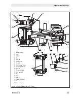
Page 17: ...p 2 Nut 3 Clamp 4 Bar 5 Screws 6 Limit switch 7 Thread 8 Anti rotation fixture 9 Mounting bracket 10 Screws 11 Follower clamp 12 Nut and bolt 13 Pin 14 Nut 15 Lever II 16 Clamp for lever 17 Nut 18 Lev...

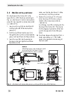
Page 18: ...sure that the short lever 1 slides over the pin 16 of the positioner 4 Replace the vent plug 17 in the posi tioner housing with the screw plug in cluded in the accessories order no 1400 6710 In excha...

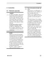
Page 19: ...specified in the EC type examination certificates ap ply when interconnecting intrinsically safe electrical equipment Ui and U0 Ii and I0 Pi and P0 Ci and C0 as well as Li and L0 Note on the selection...

Page 20: ...hile energized only during installa tion maintenance or repair Equipment connected to energy lim ited circuits with type of protection Ex nL energy limited equipment ac cording to EN 60079 15 2003 may...

Page 21: ...k plastic Order no 8808 0178 Blue plastic Order no 8808 0179 4 1 1 Switching amplifier for Type 4746 x2 For operation of the inductive limit switches switching amplifiers in accordance with EN 60947 5...

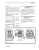
Page 22: ...and assigned to the correspond ing switching elements 3 1 4 1 4 2 42 52 42 52 41 51 43 53 41 51 43 53 A A 3 1 Adjustment screw 4 1 Metal tag 4 2 Cam disk Type 4746 x2 Inductive Limit Switch Type 4746...

Page 23: ...travel position e g final position Turn the adjustment screw 3 1 to slowly move the metal tag 4 1 towards the contact until the switching point is reached Turn the adjustment screw in the opposite di...

Page 24: ...explosion protected components on ly by original routine tested components provided by the manufacturer Devices that have already been used outside hazardous areas and are intended for future use insi...

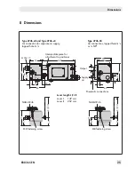
Page 25: ...x2 and Type 4746 x3 Air connection for separate air supply tapped hole G 1 8 Intermediate piece for attachment to positioner M8 fastening screw M8 fastening screw Output Supply air Pneumatic connectio...

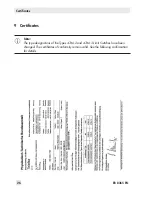
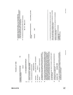
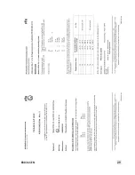
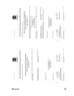
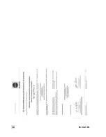
Page 26: ...EN Certificates 9 Certificates Note The type designations of the Types 4746 2 and 4746 3 Limit Switches have been changed The certificates of conformity remain valid See the following confirmation fo...

Page 27: ...EB 8365 EN 27...

Page 28: ...28 EB 8365 EN...

Page 29: ...EB 8365 EN 29...

Page 30: ...30 EB 8365 EN...

Page 31: ...EB 8365 EN 31...

Page 32: ...32 EB 8365 EN...

Page 33: ...EB 8365 EN 33...

Page 34: ...is shown in the table below Temperature class Permissible ambient temperature range Maximum short circuit current T6 T5 T4 45 C 45 C 45 C 60 C 45 C 75 C 52mA T6 T5 T4 45 C 60 C 45 C 80 C 45 C 80 C 25m...

Page 35: ...accordance with the National Electrical Code ANSI NFPA 70 Installation drawing Control Relay Hab cEx de with Model SJ b N Proximity Sensors Control Relay Terminal No Groups L mH C F V0C V ISC mA 1 3...

Page 36: ...36 EB 8365 EN...

Page 37: ...EB 8365 EN 37...

Page 38: ...38 EB 8365 EN...

Page 39: ...EB 8365 EN 39...

Page 40: ...SAMSON AG MESS UND REGELTECHNIK Weism llerstra e 3 60314 Frankfurt am Main Germany Phone 49 69 4009 0 Fax 49 69 4009 1507 samson samson de www samson de EB 8365 EN 2017 09 27 English...

Reviews: