EB 8365 EN
7
Design and principle of operation
3.1
3
5
L
10
4.1
1 1.1
2
L
3.1
3
10
7
6.2
6.1
6
4.2
1 1.1
2
L
3.1
3
4.2
1 1.1
2
10
8
6.2
6.1
6
A
1
A
2
9
9
8.2 8.1
8.1 8.2
p
z
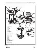
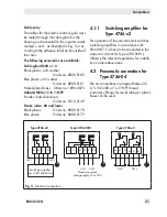
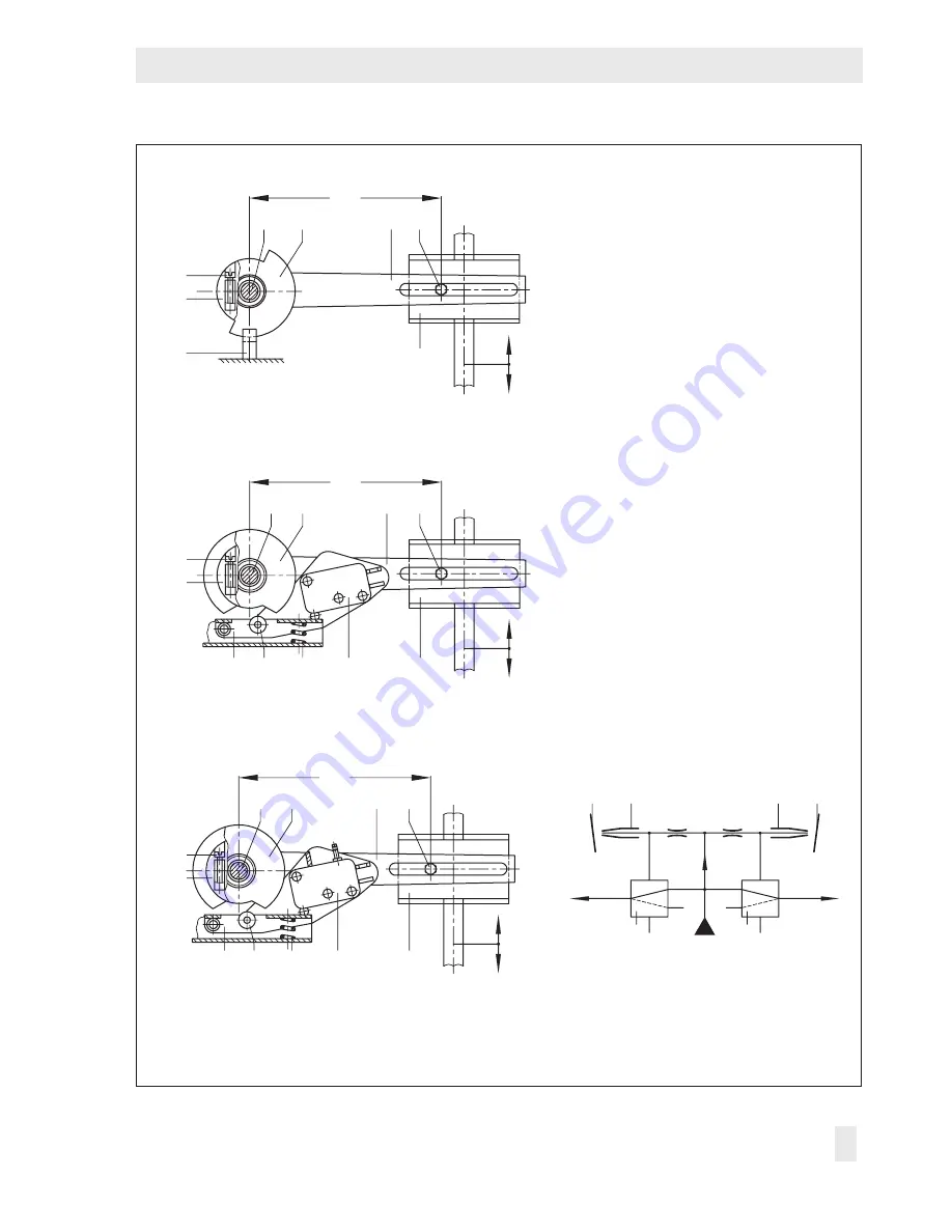
Inductive limit switch
Electric limit switch
Pneumatic limit switch with switching function
1 Lever for valve travel
1.1 Pin
2 Shaft
3 Switch case
3.1 Adjustment screw
4.1 Metal tag
4.2 Cam disk
5 Proximity switch
6 Switch lever
6.1 Roller
6.2 Spring
7 Electric switch
8 Pneumatic switch
8.1 Nozzle (in switch)
8.2 Flapper (in switch)
9 Pneumatic microswitch
10 Plate attached either to
actuator stem or plug stem
Fig. 1:
Functional drawings
Summary of Contents for 4746
Page 4: ......
Page 27: ...EB 8365 EN 27...
Page 28: ...28 EB 8365 EN...
Page 29: ...EB 8365 EN 29...
Page 30: ...30 EB 8365 EN...
Page 31: ...EB 8365 EN 31...
Page 32: ...32 EB 8365 EN...
Page 33: ...EB 8365 EN 33...
Page 36: ...36 EB 8365 EN...
Page 37: ...EB 8365 EN 37...
Page 38: ...38 EB 8365 EN...
Page 39: ...EB 8365 EN 39...


