background image

Samson AirLine

The basic procedure for setting up and using your AirLine System takes only a few minutes:

1.  For your AirLine system to work correctly, both the receiver and transmitter must be set to the same channel.  Remove all packing materi-

als (save them in case of need for future service) and check to make sure that the supplied receiver and transmitter are set to the same chan-

nel (a complete channel plan is printed on the inside back cover of this manual).  If these channels do not match, contact your distributor or, 

if purchased in the United States, Samson Technical Support at 1-800-372-6766.

2.  Physically place the receiver where it will be used (the general rule of thumb is to maintain “line of sight” between the receiver and trans-

mitter so that the person using or wearing the transmitter can see the receiver).  The CR77 can be rack-mounted if desired (taking a half-rack 

space), using an optional Samson adapter kit.  

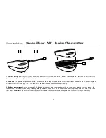
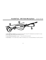
3.  Extend the receiver antenna(s) and place it (them) in a vertical position.  Make sure the Power on-off switch in your AH1 transmitter is set 

to “Off.”

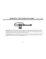
4.  Gently pry off the battery cover off the AH1 transmitter and slide it upwards and off to open the battery compartment.  Please use care 

when opening this cover as undue force will destroy the hinge.

5.  Place a fresh AAA alkaline battery in the transmitter battery compartment, taking care to observe the polarity markings.  Then replace the 

battery cover and gently press down on it until it clicks.  Leave the AH1 off for the moment.

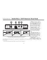
6.  Make the physical cable connection between the receiver output jack and a mic level audio input of your amplifier or mixer.  The bal-

anced XLR jack  is preferable, since it will deliver an electromagnetically cleaner signal.  If required, both the balanced and unbalanced out-

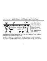
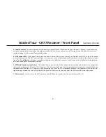
puts can be used simultaneously.  If your system contains a CR77 

receiver, be sure to set its Audio Output Level switch correctly (see


pages 7 and 9 for details).  Leave your amplifier (and/or mixer) off at this time.

7.  Turn the Volume, Level or AF Level knob on the receiver completely counterclockwise.  Connect the supplied AC adapter to the CR77 

receiver and plug it in  

then plug the adapter into any standard AC outlet.  Slide the Power switch in the direction of the arrow to turn on

 the receiver.  If your system contains a CR77 receiver, its "Power" LED will light steadily red.  

Setting Up and Using Your AirLine System


15

Summary of Contents for Airline 77

Page 1: ...U H F W I R E L E S S S Y S T E M AH1 Q Series Aerobics and Vocal Headset Transmitter AH1 HM40 Wind Instrument Transmitter CR77 Receiver OWNERS MANUAL HEADSET TRANSMITTER WIND INSTRUMENT TRANSMITTER...

Page 2: ...e instructions in the literature accompanying the appliance ATTENTION RISQUE D LECTROCUTION NE PAS OUVRIR WARNING TO PREVENT FIRE OR SHOCK HAZARD DO NOT USE THIS PLUG WITH AN EXTENSION CORD RECEPTACLE...

Page 3: ...in AT BE CH CY CZ DK EE FI FR DE GR HU IE IS IT LV LT LU MT NL NO PL PT RO SK SI ES SE UK Subject to license Please contact your national frequency authority for information on avail able legal use in...

Page 4: ...t limit your movement In this manual you ll find a more detailed description of the features of all AirLine systems as well as a guided tour through all components step by step instructions for settin...

Page 5: ...limit your movement In this manual you ll find a more detailed description of the features of all AirLine systems as well as a guided tour through all components step by step instructions for setting...

Page 6: ...fied turn the transmitter off again 4 If you are using an AH1 headset microphone position it correctly as per the illustrations on page 12 If you are using an AirLine UHF Wind Instrument System clamp...

Page 7: ...or sing into your headset microphone or play the instrument connected to the horn microphone at a normal performance level while slowly raising the audio input control of your amplifier or mixer unti...

Page 8: ...nual Reference level is obtained when the knob is turned fully clockwise to its 10 setting 3 Audio Meter This ladder display similar to the VU bar meter used on audio devices indicates the strength of...

Page 9: ...mpletely inaudible but it effectively increases overall range while virtually eliminating potential interference and phase cancellation problems 6 RF Radio Frequency Level meter This ladder display si...

Page 10: ...output level attenuation of the balanced output see 4 below to 20 dBm line level or 40 dBm mic level See Setting Up and Using the AirLine System on page 14 4 Balanced output Use this elec tronically...

Page 11: ...al operations See the Setting Up and Using the AirLine System section on page 14 in this manual for more information about antenna positioning 3 Battery compartment Insert a standard AAA alkaline batt...

Page 12: ...mute the transmission of audio signal If you don t plan on using the AH1 for extended periods turn it off power by using the power on off switch see 5 below 5 Power switch Move this switch in the dire...

Page 13: ...he microphone directly in front of your lips To avoid feedback problems take care not to cover the mic capsule with your hand IMPORTANT NOTE As shown in the illustration on the left the rear band of t...

Page 14: ...the sup plied HM40 owners manual for microphone positioning instructions 2 Samson AH1 headset transmitter See pages 13 14 in this manual for more information 3 Horn bell clamp Use this to attach the e...

Page 15: ...attery cover off the AH1 transmitter and slide it upwards and off to open the battery compartment Please use care when opening this cover as undue force will destroy the hinge 5 Place a fresh AAA alka...

Page 16: ...lit make sure that the gain structure of your audio system is correctly set consult the owners manual of your mixer and or amplifier for details If the Peak LED is lit simply move the microphone furth...

Page 17: ...ng walk through the entire area that will need to be covered As you do so observe the RF display or meter on the receiver to make sure that it is receiving sufficiently strong RF signal in the CR77 re...

Page 18: ...Minimum 3dB Maximum Frequency Stability 40kHz Minimum 40kHz Maximum Spurious 1 W Modulation Factor 13kHz Minimum 15kHz Typical 17kHz Maximum Input 1kHz 20dBv Input Impedance Mic 2K ohms THD 2 1 kHz de...

Page 19: ...Temperature 0 C 50 C Operating Voltage 15 Volts 10 Current Consumption 160 mA all LED lights illuminated Sensitivity 18 dBm THD 2 Squelch Sensitivity 0 40 dBm Adjustable Selectivity 150 kHz AF Out Ra...

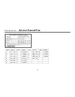
Page 20: ...Samson AirLine AirLine Channel Plan 20...

Page 21: ......

Page 22: ...Samson Technologies Corp 45 Gilpin Avenue Hauppauge New York 11788 8816 Phone 1 800 3 SAMSON 1 800 372 6766 Fax 631 784 2201 www samsontech com Samson Manual for Airline AH1 091005 v4 4...

Reviews: