background image

EB 8075 EN


 3-13

Design and principle of operation

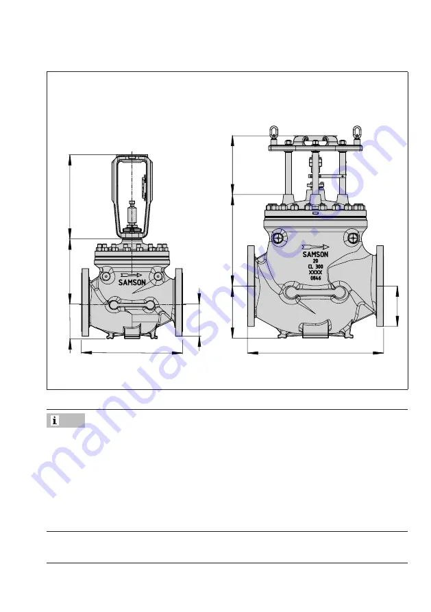
Dimensional drawings

H2

H5

L

H8

H4

H2

H5

L

H8

H4

Type 3591 Valve · NPS 10 to 12 and 

NPS 16 (Class 150)

Type 3591 Valve · NPS 16 (Class 300 and 
higher) to 32

Refer to the following data sheet for more dimensions and weights:

u

 T 8075

The associated actuator documentation applies to actuators, e.g. for SAMSON pneumatic 

actuators:

u

 T 8310-1 for Type 3271 Actuator with 750 cm² actuator area and larger

u

 T 8310-2 for Type 3271 Actuator with 1000 cm² actuator area and larger

u

 T 8310-3 for Type 3271 Actuator with 1400-60 cm² actuator area

u

 T 8312 for Type 3273 Hand-operated Actuator

Note

Summary of Contents for EB 8075 EN

Page 1: ...original instructions EB 8075 EN Edition June 2020 Type 3591 Valve ANSI version In combination with an actuator e g a Type 3271 Pneumatic Actuator Type 3591 1 Control Valve Type 3591 with hydraulic p...

Page 2: ...If you have any questions about these instructions contact SAMSON s After sales Service aftersalesservice samsongroup com Documents relating to the device such as the mounting and operating instructi...

Page 3: ...Accessories 3 6 3 5 Technical data 3 6 4 Shipment and on site transport 4 1 4 1 Accepting the delivered goods 4 1 4 2 Removing the packaging from the valve 4 1 4 3 Transporting and lifting the valve 4...

Page 4: ...and operating supplies 9 1 10 Decommissioning 10 1 11 Removal 11 1 11 1 Removing the valve from the pipeline 11 2 11 2 Removing the actuator from the valve 11 2 12 Repairs 12 1 12 1 Returning devices...

Page 5: ...alve is not suitable for the following applications Use outside the limits defined during sizing and by the technical data Use outside the limits defined by the valve accessories connected to the valv...

Page 6: ...no longer meet the requirements for its intended use Safety features The fail safe position of the control valve upon air supply or control signal failure depends on the actuator used see associated a...

Page 7: ...d observe the specified hazard statements warnings and caution notes Furthermore operating personnel must be familiar with the applicable health safety and accident prevention regulations and comply w...

Page 8: ...from all the plant sections concerned as well as the valve For oxygen service Manual u H 01 The packaging of valve constructed and sized for oxygen service has the following label on it Sauerstoff Ox...

Page 9: ...r deafness due to loud noise The noise emissions depend on the valve version plant facilities and process medium Wear hearing protection when working near the valve Risk of personal injury due to exha...

Page 10: ...ase any stored energy in the actuator e g spring compression See associated actuator documentation Risk of personal injury due to preloaded springs Valves in combination with pneumatic actuators with...

Page 11: ...ICE Risk of valve damage due to contamination e g solid particles in the pipeline The plant operator is responsible for cleaning the pipelines in the plant Flush the pipelines before start up Risk of...

Page 12: ...through the use of unsuitable lubri cants and or contaminated tools and components If necessary keep the valve and the tools used free from solvents and grease Make sure that only suitable lubricants...

Page 13: ...eal ME metal HA carbide metal ST metal base material with Stellite facing KE ceramic PT PTFE soft seal PK PEEK soft seal 13 Seat code trim material on request 14 Pressure balancing DIN D ANSI JIS B Ve...

Page 14: ...nd piston of the valves have an item number written on them You can con tact us stating this item number to find out which material is used Additionally a seat code is used to identify the trim materi...

Page 15: ...able either with a clamped or flanged seat 4 The seat is inserted into the seat bridge in the version with clamped seat The seat and cage are clamped into place by tightening the body nuts 14 The seat...

Page 16: ...3 2 EB 8075 EN Design and principle of operation 126 17 4 124 5 2 60 1 Fig 3 1 Type 3591 with flanged seat NPS 10 to 12 Class 150 to 900 and NPS 16 Class 150...

Page 17: ...8075 EN 3 3 Design and principle of operation 15 13 14 2 17 126 124 50 49 5 36 160 129 127 4 1 102 103 148 60 180 8 162 164 44 45 51 163 Fig 3 2 Type 3591 with flanged seat NPS 16 to 28 Class 300 to 9...

Page 18: ...cing 45 Gasket pressure balancing 49 Screw pressure balancing 50 Washer pressure balancing 51 Guide rings pressure balancing 60 Yoke assembly with anti rotation fixture 180 102 Snap ring 103 Retaining...

Page 19: ...ctions of the pneumatic actuator u EB 8310 X for Type 3271 A double acting piston actuator does not have a defined fail safe action as it does not contain a spring assembly 3 2 Versions With insulatin...

Page 20: ...e in creased safety e g in cases where the valve is freely accessible to untrained staff a safe ty guard must be installed to rule out a crush hazard arising from moving parts actuator and piston stem...

Page 21: ...rmissible operating pressures acc to pressure temperature diagram see Information Sheet u T 8000 2 Body without insulating section 10 to 220 14 to 428 3 10 to 220 14 to 428 3 10 to 220 14 to 428 3 10...

Page 22: ...65 640 in 9 49 11 06 13 39 19 69 22 24 25 20 Class 600 mm 271 301 360 515 595 670 in 10 67 11 85 14 17 20 28 23 43 26 38 Class 900 mm 291 331 380 535 615 700 in 11 46 13 03 14 96 21 06 24 21 27 56 H5...

Page 23: ...33 74 43 98 47 83 Class 900 mm 485 479 724 877 917 1117 in 19 09 18 86 28 50 34 53 36 10 43 98 H8 for actu ator 175 to 350 cm mm in 355 to 750 cm mm in 1000 to 1400 60 cm mm 419 419 in 16 50 16 50 140...

Page 24: ...Class 600 mm 755 822 1111 1378 1686 2111 4 in 29 74 32 37 43 74 54 27 66 36 83 18 4 Class 900 mm 994 1133 1432 1613 1873 2271 4 in 39 12 44 62 56 38 63 49 73 74 89 46 4 Length L welding ends 2 Class...

Page 25: ...1400 60 cm kg 450 490 680 1000 lbs 992 1080 1499 2205 1400 120 to 2800 cm Travel FA 30 to 75 FE 30 to 38 kg 500 540 720 1040 lbs 1102 1190 1587 2293 1400 120 to 2800 cm Travel FA 90 to 120 FE 60 to 12...

Page 26: ...50 lbs 3968 5357 7165 20 kg 2470 3000 3960 5820 lbs 5445 6614 8730 12831 24 kg 3180 4420 6050 8580 lbs 7011 9744 13338 18916 28 ASME B16 47 Flange form A kg 4890 6280 8740 12440 lbs 10781 13845 19268...

Page 27: ...ollowing data sheet for more dimensions and weights u T 8075 The associated actuator documentation applies to actuators e g for SAMSON pneumatic actuators u T 8310 1 for Type 3271 Actuator with 750 cm...

Page 28: ...3 14 EB 8075 EN...

Page 29: ...al data section 4 2 Removing the packaging from the valve Observe the following sequence Do not open or remove the packaging until immediately before lifting to install the valve into the pipeline Lea...

Page 30: ...s NPS 16 and larger Class 300 and higher bear the entire load Do not attach load bearing slings to the actuator handwheel or any other parts Observe lifting instructions see sec tion 4 3 2 A swivel ho...

Page 31: ...e the corrosion protection paint surface coatings Repair any damage immediately Protect the piping and any mounted valve accessories against damage Protect the control valve against moisture and dirt...

Page 32: ...e additional sling be tween the lashing point on the actuator and rigging equipment hook shackle etc does not bear any load when lifting valves with an actuator that has a lifting eyelet eyebolt on it...

Page 33: ...position against slipping or tipping over Do not damage the corrosion protection paint surface coatings Repair any damage immediately Protect the control valve against moisture and dirt Store it at a...

Page 34: ...4 6 EB 8075 EN Shipment and on site transport...

Page 35: ...ion Pipeline routing The inlet and outlet lengths see Table 5 1 vary depending on several variables and process conditions and are intended as rec ommendations Contact SAMSON if the Table 5 1 Inlet an...

Page 36: ...g position Generally we recommend installing the valve with the actuator upright and on top of the valve Contact SAMSON if the mounting posi tion is not as specified above Support or suspension The pl...

Page 37: ...Markings on the device section for nameplate details The requested or required additional pipe fittings see the Additional fittings section have been installed or prepared as necessary before installi...

Page 38: ...erating instructions of the hand operated actuator handwheel to mount the anti rotation fixture u EB 8312 X a Versions up to NPS 16 Class 150 See Fig 5 2 and Fig 5 3 1 Insert ball bearings 310 into th...

Page 39: ...ally tighten the screws 303 in a crisscross pattern Observe the tightening torques specified in Table 5 2 Table 5 2 Tightening torques Screw size Tightening torque Nm M12 50 M16 121 13 Check and ensur...

Page 40: ...0 310 92 84 85 255 Legend 3 Yoke 82 Screws 83 Hanger 84 Travel indicator scale 85 Screws 92 Castellated nut 255 Warning label 310 Ball bearing Piston stem Fig 5 2 Overview of yoke assembly with travel...

Page 41: ...301 309 309 9 303 304 114 Y 1 0 0 5 Y 1 0 0 5 Legend 9 Stem 114 Lubricant Gleitmo 1763 V 301 Clamps 303 Screws 304 Washers 309 Sliding washers Fig 5 3 Overview of anti rotation fixture assembly for v...

Page 42: ...181 150 52 55 1400 120 15 87 5 105 236 180 61 115 30 0 0 191 225 48 76 30 75 90 221 195 61 100 60 0 0 308 255 61 185 60 50 60 191 225 48 76 2800 5600 30 0 0 191 225 48 76 30 100 120 221 195 61 100 60...

Page 43: ...EB 8075 EN 5 9 Installation H G H F H N H O H L H T H K H I Fig 5 4 Dimensional drawing with mounting dimensions...

Page 44: ...rs 180 11 Mount the anti rotation fixtures 180 1 and 180 2 in such a way that they surround the column of the yoke to which the travel indicator scale is at tached Observe tightening torques Tightenin...

Page 45: ...he actuator from the valve or ensure it cannot transmit any forces to the actuator stem before removing the anti rotation fixture on the plug stem Depending on the version SAMSON control valves are ei...

Page 46: ...and the actual welding operations on the valve This also applies to any required heat treatment to be performed on the valve Only allow qualified welding personnel to carry out welding operations Pre...

Page 47: ...s into the pipeline 4 Attach supports or suspensions 5 4 Testing the installed valve Risk of bursting due to incorrect opening of pressurized equipment or components Valves and pipelines are pressure...

Page 48: ...or when the valve opens or closes Wear eye protection when working in close proximity to the control valve Risk of personal injury due to preloaded springs Actuators with preloaded springs are under...

Page 49: ...ve NPS 16 and larger Class 300 and higher tighten the nuts on the packing gland in a crisscross pattern by turning them clockwise until the packing seals the valve 2 Open and close the valve several t...

Page 50: ...6 EB 8075 EN Installation During the pressure test make sure the fol lowing conditions are met Retract the piston to open the valve Observe the maximum permissible pres sure for both the valve and pla...

Page 51: ...ion or pneumatic valve accessories not fitted with noise reducing fittings Both can damage hearing Wear hearing protection when working near the valve Crush hazard arising from moving parts actuator a...

Page 52: ...sizing requirements see information under Intended use in the Safety instructions and measures section Start up putting the valve back into opera tion 1 Allow the valve to cool down or warm up to rea...

Page 53: ...c valve accessories not fitted with noise reducing fittings Both can damage hearing Wear hearing protection when working near the valve Crush hazard arising from moving parts actuator and piston stem...

Page 54: ...e handwheel of valves with actuators fitted with a handwheel must be in the neutral po sition during normal operation 7 2 Manual operation Valves with actuators fitted with a handwheel can be manually...

Page 55: ...t and lock the pneumatic air supply as well as the control signal Before unblocking the actuator release any stored energy in the actuator e g spring compression See associated actuator documentation...

Page 56: ...service The valve leaks to the atmosphere fugitive emissions Defective packing Contact our after sales service Version with adjustable packing 1 packing not tightened correctly Adjust the packing see...

Page 57: ...off valves upstream and downstream of the control valve to stop the process medium from flowing through the valve 2 Perform troubleshooting see sec tion 8 1 3 Rectify those malfunctions that can be r...

Page 58: ...8 4 EB 8075 EN...

Page 59: ...Certain test results certified by SAMSON lose their validity when the valve is opened Such testing includes seat leakage and leak tests The product warranty becomes void if ser vice or repair work not...

Page 60: ...9 2 EB 8075 EN...

Page 61: ...m up to the ambient tem perature Wear protective clothing and safety gloves Risk of personal injury due to pressurized components and process medium being discharged Do not loosen the screw of the tes...

Page 62: ...residual process medium in the valve While working on the valve residual me dium can flow out of the valve and depend ing on its properties cause personal injury e g chemical burns Wear protective clo...

Page 63: ...n the actuator e g spring compression See associat ed actuator documentation Risk of personal injury due to residual process medium in the valve While working on the valve residual me dium can flow ou...

Page 64: ...ipeline a Version with flanges 1 Support the valve to hold it in place when separated from the pipeline see the Shipment and on site transport sec tion 2 Unbolt the flange joint 3 Remove the valve fro...

Page 65: ...After sales Service 2 Send an e mail u retouren samsongroup com to register the return shipment including the following information Type Article no Configuration ID Original order Completed Declaratio...

Page 66: ...12 2 EB 8075 EN...

Page 67: ...EB 8075 EN 13 1 Disposal 13 Disposal Observe local national and internation al refuse regulations Do not dispose of components lubricants and hazardous substances together with your household waste...

Page 68: ...13 2 EB 8075 EN...

Page 69: ...Equipment Directive 2014 68 EU is provided on the next page The certificate shown was up to date at the time of publishing The latest certificates can be found on our website u www samsongroup com Pr...

Page 70: ...14 2 EB 8075 EN...

Page 71: ...ure balancing 45 Gasket pressure balancing 49 Screw pressure balancing 50 Washer pressure balancing 51 Guide ring several guides only for version with graphite seal 82 Screw 83 Hanger 84 Travel indica...

Page 72: ...15 2 EB 8075 EN 160 129 50 44 51 127 4 1 124 5 49 126 103 102 17 45 36 13 14 11 8 2 15 18 19 16 91 Type 3591 Flanged seat NPS 10 to 16 Class 150...

Page 73: ...EB 8075 EN 15 3 85 82 309 3 9 92 310 309 301 84 83 301 304 303 255 85 309 3 9 92 310 309 301 84 83 301 304 303 255 82 85 309 3 9 92 310 309 301 84 83 301 304 303 255 82...

Page 74: ...de rings 54 Pressure balancing assembly 60 Yoke assembly 180 1 Anti rotation fixture front 180 2 Anti rotation fixture back 180 3 Adapter 180 4 Retaining washer 180 5 Hex screw 180 6 Stem connector nu...

Page 75: ...EN 15 5 180 8 180 7 3 5 3 3 3 6 148 3 2 180 4 180 3 3 1 82 84 162 164 8 2 13 163 180 2 180 12 127 1 4 160 103 124 102 5 51 44 126 180 6 17 3 4 14 180 1 180 10 36 180 5 15 180 11 49 50 45 129 180 9 12...

Page 76: ...e addresses of SAMSON AG its subsid iaries representatives and service facilities worldwide can be found on our website www samsongroup com or in all SAMSON product catalogs Required specifications Pl...

Page 77: ......

Page 78: ......

Page 79: ......

Page 80: ...2021 10 19 English SAMSON AKTIENGESELLSCHAFT Weism llerstra e 3 60314 Frankfurt am Main Germany Phone 49 69 4009 0 Fax 49 69 4009 1507 samson samsongroup com www samsongroup com EB 8075 EN...

Reviews: