background image

®

EX10 • EX20 • EX30

OWNERS MANUAL

Summary of Contents for Expedition EX10

Page 1: ...EX10 EX20 EX30 OWNERS MANUAL...

Page 2: ...inted March 2000 Samson Technologies Corp 575 Underhill Blvd P O Box 9031 Syosset NY 11791 9031 Phone 1 800 3 SAMSON 1 800 372 6766 Fax 516 364 3888 Table of Contents Introduction 3 System Features 4...

Page 3: ...able including a 500 watt active subwoofer our EX500 a rechargable Lead Acid GelCel battery pack and a rear panel mountable cassette recorder with pitch control There s even a prewired custom compartm...

Page 4: ...diaphragm along with a phasing plug for linear response and an elliptical wave guide horn design that reduces nearly all sonic diffraction A tilt position that allows the Expedition to be used as an o...

Page 5: ...udio performance already proven on stages around the world Receivers supported include the UM1 or M32 UHF models or the VM1 VHF model A wide range of optional accessories including the MP 1030 mountin...

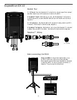
Page 6: ...hain one EX10 to another See below for interconnection diagrams 4 Speakon extension Alternatively you can use this Speakon connector to daisy chain one EX10 to another See below for interconnection di...

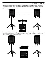
Page 7: ...tion is made between either the 1 4 extension to a second EX10 s input solid line or between the Speakon extension to a second EX10 s Speakon input dotted line Using two EX10s in stereo A stereo signa...

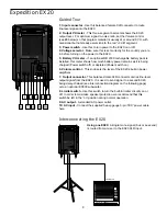
Page 8: ...r remains as it is being charged Power switch off or depleted Power switch on 6 Volume control This knob sets the level of the EX20 s built in power amplifiers 7 Output connector This balanced male XL...

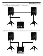
Page 9: ...signal bus or aux send is routed from a mixer to one EX20 s XLR input and a connection is made between that EX20 s XLR output to a second EX10 s XLR input Using two EX20s in stereo A stereo signal bus...

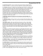
Page 10: ...al anywhere in the left right stereo spectrum while keeping the overall signal level constant When the knob is placed at its center detented position the signal is sent equally to both the left and ri...

Page 11: ...left at the mixer the Right output can then be used to send signal from the right output section that is signal panned right at the mixer to a second enclosure See the interconnection diagrams on page...

Page 12: ...t in the on position during normal operation 18 Voltage selector Make sure this is set correctly for the country you are in before turning on the power to the EX30 19 Gain switch Sets the line level T...

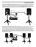
Page 13: ...one EX30 and three EX20s extended range stereo operation In this example microphones are connected to the XLR mic inputs of channels 1 and 2 of an EX30 and a stereo keyboard is connected to the stereo...

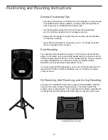
Page 14: ...tains a 1 3 8 stand mount socket that allows it to be raised up on any standard speaker pole mounting such as the Ultimate Support Systems TS 30 or TS 33 speaker stands Pole mounting is generally advi...

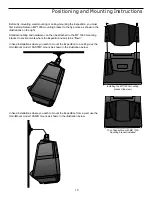
Page 15: ...e MP 1030 mounting bracket in environments where the Expedition needs to be flown In fixed installations where you wish to mount the Expedition to a ceiling use the OmniMount model 100 STMP mount as s...

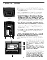
Page 16: ...controls A set of standard transport controls from left to right Record Play Rewind Fast Forward Stop Eject Pause Both the Record and Play buttons must be pressed in simultaneously to record signal 2...

Page 17: ...coil Kapton Former 50 oz barium ferrite magnet HF Driver all models 1 compression driver Stereo Mixer Section EX30 only Inputs 2 Mic Line XLR TRS 1 Stereo Line w Mic TRS RCA XLR Outputs 4 Balanced XLR...

Reviews: