background image

5

Controls and Functions

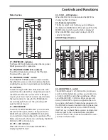
INPUT CHANNEL SECTION - continued

around the center point that are affected by the MID 

CUT & BOOST control) and can be set in a range from 

100Hz to 8Khz. 

LF (LOW FREQUENCY) 80Hz +/- 15dB shelving 

type

The channel’s LOW frequency response is flat when 

the knob is in the “12:00” position. Rotating the 

knob towards the right will boost the channel's low 

frequency response at 80 Hertz by 15dB, and rotating 

it towards the left will cut the frequency by 15dB. 

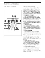
8 - Channel Equalizer - Stereo Channels

The L1200 and L2000 Stereo input channels feature 

a 4-band equalizer allowing you to adjust the high, 

mid, and low frequencies independently on each 

channel. The stereo channel equalizer is laid out like 

a mono input on the control panel input strip, but 

internally, the equalizer is affecting a stereo signal 

path. The channel’s frequency response is flat when 

the knobs are in the “12:00” position. Rotating the 

knob towards the right will boost the corresponding 

frequency band by 15dB, and rotating it towards the 

left will cut the frequency by 15dB. The frequency 

centers, range of boost or cut, and equalizer type for 

each band are as follows:
High: 12kHz +/- 15dB shelving type
High Mid: 3kHz +/- 15dB peaking type
Lo Mid: 500 kHz +/- 15dB peaking type
Low: 80Hz +/- 15dB shelving type

9 - PAN Control

The L1200 and L2000’s PAN control is used to place 

or position the mono signal into the stereo main Left 

and Right MIX bus. You can create a stereo image by 

panning some input signals to the left and others 

to the right. The L1200 and L2000’s PAN control is a 

Power-Pan circuit, which includes a 3dB dip in the 

center position.  This is desirable since there’s a 3dB 

increase in gain when the mono input signal is heard 

in both the Left and Right MIX bus. 

10 - MUTE switch  

The Mono Input channels feature a large, backlit 

MUTE switch allowing you to easily turn that channel 

on or off. When MUTE switch is illuminated, the 

channel is off. Conversely, when the backlight is off, 

the channel is on. 

11 - SOLO/PFL (Pre Fader Listen) switch 

The Mono Input channel’s PFL, or Pre Fader Listen 

switch allows you to listen, or “solo” a channel or 

group of channels in the headphones. When the 

SOLO/PFL switch is pressed down, either mono PFL 

or stereo SOLO is sent to the headphones. To listen 

to the PFL, press the Meter Select switch, located 

below the VU meter, down to select PFL. To hear the 

stereo SOLO, the meter switch must be in the up 

position.

12 - 1-2 Group Assign switch

The 1-2 Group assign switch is used to assign the 

input channel to the 1-2 Group output bus. 

Note:

 The Group output follows the channel’s PAN 

control, so if a channel is panned all the way to the 

left it will only feed Group Output 1. Conversely, if a 

channel is panned all the way to the right, it will only 

feed Group Output 2.

13 – 3-4 Group Assign switch

The 3-4 Group assign switch is used to assign the 

input channel to the 3-4 Group output bus. 

Note:

 The Group output follows the channel’s PAN 

control so if a channel is panned all the way to the 

left, it will only feed Group Output 3. Conversely, if a 

channel is panned all the way to the right, it will only 

feed Group Output 4.

14 –MAIN  Assign switch

The MAIN assign switch is used to assign the input 

channel to the left and right stereo bus outputs. 

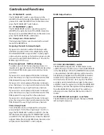
15-  VOLUME - Fader Level Control

The VOLUME Fader control adjusts the level of each 

mono input channel.

Summary of Contents for LI200

Page 1: ...Front of House Mixing Consoles 4 BUS MIXING CONSOLE WITH USB I O 24BIT DIGITAL EFFECTS...

Page 2: ...product Important Safety Instructions 1 Please read all instructions before operating the unit 2 Keep these instructions for future reference 3 Please heed all safety warnings 4 Follow manufacturers i...

Page 3: ...ridurre il rischio di incendio o di scariche elettriche non esponete questo apparecchio a pioggia o umidit Per ridurre il pericolo di scariche elettriche evitate di rimuoverne il coperchio o il pannel...

Page 4: ...Equalizer 8 USB I O Section 8 Meter Section 9 Group Output Section 9 Main Output Section 10 L1200 And L2000 Input And Output Connections 11 12 Using The Usb I o 14 Getting Started With Windows XP 14...

Page 5: ...ord a completely independent mix The L1200 and L2000 will give you clean clear sound reproduction thanks to the advanced circuit topology high quality components low noise discrete microphone preamps...

Page 6: ...nal Processor multi effects processors with 100 selectable presets offering dazzling studio quality effects including Reverb Delay Chorus and Flanging The L Series mixers feature high quality low nois...

Page 7: ...an external monitor system These buses start by sending the signal from each individual channel which is set with one of the auxiliary control knobs Then the mix of all the channels auxiliary level is...

Page 8: ...AUX 3 is sent after the fader so the channel Fader has an effect on that level meaning the Aux level tracks up and down with the channel Fader This is the normal setting for using AUX 3 as an effects...

Page 9: ...includes a 3dB dip in the center position This is desirable since there s a 3dB increase in gain when the mono input signal is heard in both the Left and Right MIX bus 10 MUTE switch The Mono Input c...

Page 10: ...n DSP effects presets The first bank of 10 presets have been programmed with common effects for live performance and the following banks are set up in groups by the types of effects 18 SELECT control...

Page 11: ...vel controls to set the amount of signal being sent to Aux 2 Output 26 AUX 3 Master Send The Aux 3 signals from mono and stereo input chan nels along with the DSP returns are mixed together and sent t...

Page 12: ...g most any recording and or playback software The INPUT and ASSIGN switch give you added flexibility in routing the digital audio signal to and from the PC 34 SEND USB input send switch The USB INPUT...

Page 13: ...er select switch the meters will display the MAIN MIX mono PFL or Stereo Solo 42 PFL LED indicator When the PFL LED is illuminated the METER is displaying the PFL level 37 38 39 41 43 44 42 40 43 SOLO...

Page 14: ...e overall level of the GROUP mix Assigning Channels to Group Outputs If you want to control a number of channels with one fader you can create a mix subgroup by using the channel GROUP assign switches...

Page 15: ...el use only one of the inputs as appro priate for the input source 3 INSERT Send and Return jack The L1200 and L2000 have a 1 4 inch TRS TIP 1 2 3 RING SLEEVE Insert jack for connecting outboard effec...

Page 16: ...led by the CD Tape level control 9 Record Out RCA jacks The signal present at this connector is the MAIN bus signal before it has passed through the MASTER level control The nominal output level is 10...

Page 17: ...witch connected to this jack you can turn on and off the on board digital effects by sim ply stepping on the footswitch 18 PHONES 1 4 inch jack top Panel Connect standard stereo headphone 60 to 600 Oh...

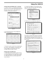
Page 18: ...ctions of this manual Getting Started with Windows XP 1 The first time you plug the L series into a USB port Windows will install the universal drivers for that port A balloon tip will pop up telling...

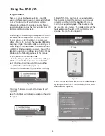
Page 19: ...C OS X 1 Connect the L Series console to your mac using a standard USB cable The LED will light to indicate it is receiving USB power The MAC will recognize the USB audio device and automatically inst...

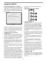
Page 20: ...so assign the USB out to feed from the AUX1 and AUX2 outputs enabling you to build a stereo mix for recording that s independent from the house sound system Press the USB SEND Figure 11 switch down to...

Page 21: ...CONNECTING THE L1200 and L2000 There are several ways to interface the L1200 and L2000 to support a variety of applications The L1200 and L2000 fea ture balanced inputs and outputs so connecting balan...

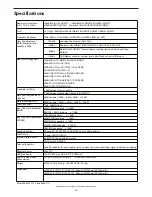
Page 22: ...2000 27 4 W 15 9 D 4 9 H 696mm W 403mm D 125mm H 24 BIT DSP 100 selectable presets Peak An indicator for each channel turns on when the pre channel fader signal is 5dB below clipping Input Channel Equ...

Page 23: ...19 Block Diagram...

Page 24: ...Samson Technologies Corp 45 Gilpin Avenue Hauppauge New York 11788 8816 Phone 1 800 3 SAMSON 1 800 372 6766 Fax 631 784 2201 www samsontech com...

Reviews: