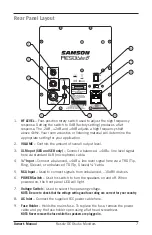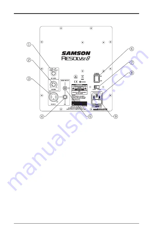
Rear Panel Layout
1.
HF LEVEL – Four-position rotary switch used to adjust the high frequency
response. Setting the switch to 0dB (factory setting) produces a flat
response. The -2dB, +2dB and +4dB adjusts a high frequency shelf
above 4kHz. Your room acoustics or listening material will determine the
appropriate setting for your application.
2.
VOLUME – Controls the amount of overall output level.
3.
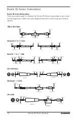
XLR Input (SE6 and SE8 only) – Connect a balanced, +4dBu, line level signal
here via standard XLR (microphone) cable.
4.
¼” Input – Connect a balanced, +4dBu, line level signal here via a TRS (Tip,
Ring, Sleeve), or unbalanced TS (Tip, Sleeve) ¼”cable.
5.
RCA Input – Used to connect signals from unbalanced, –10dBV devices.
6.
POWER Switch – Use this switch to turn the speakers on and off. When
powered on, the front panel LED will light.
7.
Voltage Switch – Used to select the operating voltage.
NOTE: Be sure to check that the voltage setting and fuse rating are correct for your country.
8.
AC Inlet – Connect the supplied IEC power cable here.
9.
Fuse Holder – Holds the mains fuse. To replace the fuse, remove the power
cable and pry the fuse holder open using a flat head screwdriver.
NOTE: Never remove the fuse while the speakers are plugged in.
Owner's Manual
7
Resolv SE Studio Monitors
Summary of Contents for RESOLV5e
Page 1: ...OWNER S MANUAL...


