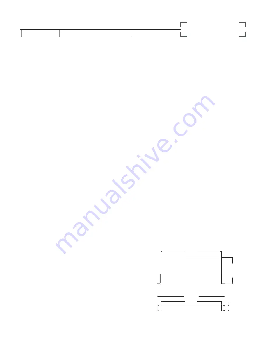
430mm
430mm
44mm
482.6mm
188.1m
m
TOP
FRONT
S
•
COM PLUS
PRODUCT SPECIFICATION SHEET
SERIES
DESCRIPTION
CATEGORY
S•CLASS
MULTI-ZONE STEREO MIXER
SIGNAL PROCESSING
S•COM PLUS SPECIFICATIONS
System Specifications
Frequency Response ........... <10Hz to 20kHz +0 / -0.1 dB
effect out, -0.4 @ 100kHz,
<10Hz to 20kHz +0 / -0.1 dB
effect in, -3dB @ >100kHz
Dynamic range .................... 116 dB, un-weighted, 22 Hz
to 22 kHz
THD .................................. 0.008 % typ. @ +4 dBu, 1 kHz
Effect out, 0.016% effect in
Crosstalk ............................ >100dB, 22 Hz to 22 kHz
Operating Level .................. Sele4dBu / -10 dBV
Max. Input Level ................. +21dBu, balanced
CMRR ................................ Min. 40dB, >50dB @ 1kHz
Max. Output Level ............... +21dBu, balanced
Signal Input
Connectors ......................... XLR and 1/4" TRS jack
Impedance ......................... >20K Ohms balanced or
>10K unbalanced
Signal Output
Connectors ......................... XLR and 1/4" TRS jack
Impedance ......................... 60 Ohms balanced or 30
unbalanced
Key Input
Connector .......................... 1/4" jack
Impedance ......................... 10 k Ohm
Max. Input Level ................. +21 dBu
Key Output
Connector .......................... 1/4" jack
Impedance ......................... 47 Ohms
Max. Output Level ............... +21 dBu
Expander/Gate
Trigger range ...................... Variable (Off to +10 dB)
Attack ................................ <1 ms per 50 dB
Release .............................. Variable (Slow:100 ms / 1dB,
Fast:100 ms / 100 dB)
Ratio ................................. Expander 2:1, Gate 16:1
Compressor Section
Detector ............................. RMS
Threshold ........................... -40 dB to +20 dB
Ratio ................................. Variable (1:1 to infinity : 1)
Manual Attack Time ............ Variable (0.3 ms / 20 dB to
300 ms / 20dB)
Manual Release Time .......... Variable (0.05 to 5 Sec)
Output gain ........................ Variable (-20 to +20 dB)
Peak Limiter Section
Threshold ........................... Variable 0dB to Off
Ratio ................................. Preset
Limiter ............................... Ceiling type
Attack ................................ <5 ms
Release .............................. Typ. 20dB/s
De-Esser
Level range ........................ variable (0 to 10dB)
Maximum ........................... 12dB Gain Reduction mid /
high band
Function Switches
Gate .................................. Gate or Expander
Release .............................. Fast/slow
Enhancer ........................... In/Out
In/Out (1,2) ........................ Bypass
Key .................................... Switches the detector section
to external key input
Auto .................................. Sets automatic attack and
release times - program
dependent
I/O Meter ........................... Switches the Input/Output meter
to read input or output level
In/Out ................................ De-Esser
Stereo Link ......................... Links both channels for
stereo operation. Channel 1
becomes Master.
Level (Rear Panel) ................. Changes the internal reference
level from +4dBu to -10dBV
Meters & LED's
Gain Reduction ................... 12 segment LED display: 30 /
27 / 24 / 21 / 18 / 15 / 12 / 9 /
6 / 4 / 2 / 1dB
Input/Output level ............... 12 segment LED display: -30 /
-24 / -18 / -12 / -6 / -3 / 0 /
+3 / +6 / +9 / +12 / +18dB
Expander/Gate Threshold ..... 2 LED'S Gate open, Gate closed
Peak Limiter Threshold ........ 1 LED for Indication of
Limiter function
Function switch .................. LED indicator in each (except
Level switch)
Power Supply
Mains Voltages USA/Canada ... 105 - 125 VAC ~, 60 Hz
Mains Voltages Europe ........ 215 - 254 VAC~,50 / 60Hz
Power Consumption ............ 10 Watts
Power inlet ......................... Standard IEC receptacle/with fuse
Physical
Dimensions ........................ 1 3/4 (44.5 mm) x 19
(482.6 mm) x 7 3/4 (188 mm)
Net Weight ......................... 5 lbs., (2.3 kg)
Shipping Weight ................. 7.5 lbs., (3.4 kg)
ARCHITECT’S & ENGINEER’S SPECIFICATIONS
(continued)
Level control shall be on the front panel. A variable de-esser
with an In and Out switch for removing sibilance shall on the
front panel. Each channel shall have a switchable enhancer to
bring back the high frequencies lost do to heavy compression.
Full LED Gain Reduction and Input/Output metering will be
on both channels with a I/O meter switch to select input or
output viewing on the meter. The unit shall have front panel
bypass switches and a Stereo Link switch. A standard IEC
power cable shall be provided to connect to AC power.


