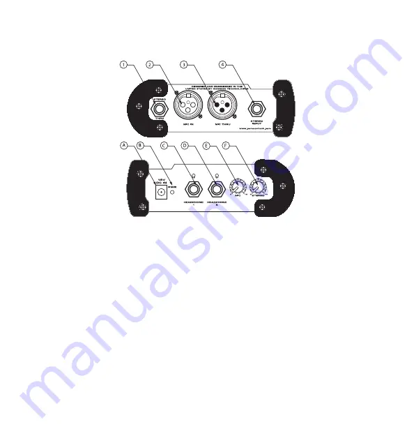
S monitor Front and Rear Panel Layout
A
DC POWER INPUT
- Connect the sup-
plied power adapter here.
B
POWER LED -
Red LED will illuminate
when power is on indicating the S mon-
itor is ready for operation.
C
PHONE 1
- 1/4” output for connecting
headphones.
D
PHONE 2
- 1/4” output for connecting
headphones.
E
MIC VOLUME
- Control knob used to
adjust the level of the MIC input signal.
F
MIX VOLUME
- Control knob used to
adjust the level of the Stereo input sig-
nal.
1
STEREO THRU
- 1/4-inch TRS (TIP/
RING/SLEEVE) connector to output
main stereo signal.
2
MIC INPUT
- Connect any dynamic
or battery powered condenser
microphone here.
3
MIC THRU
- Parallel output for pass-
ing microphone signal to main
mixer.
4
STEREO INPUT
- 1/4-inch TRS (TIP/
RING/SLEEVE) connector to input
main stereo signal.(Tip = Left; Ring
= Right)
4


