


9
Operating the S•phone
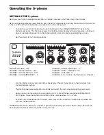
STEREO AND TWO-CHANNEL MODES
Each of the S•phone’s four channels can be set to operate in two different modes: Stereo and 2 Channel.
Stereo Mode
Stereo mode is a normal operating mode where all mix inputs including MAIN, MASTER INJECT, as well as the
Channel AUX input, maintain their stereo image throughout the signal path to each headphone output. The indi-
vidual Channel’s PAN control is used to adjust the balance between the Left and Right side. To design a monitor
mix in the Stereo mode, follow these steps:
•
Press the ST/2CH switch to the OUT positions, you’ll notice the switch LED is not illuminated indicating
that Channel 1 is in STEREO mode.
•
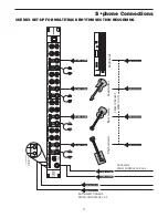
Make a Stereo connection from your mixer’s auxiliary or buss outputs to the MAIN Left and Right inputs
on the S•phone’s rear panel.
•
Make a Stereo connection from your mixer’s auxiliary or buss outputs to the MASTER INJECT input on
the S•phone’s front panel.
•
Make a Stereo connection from your mixer’s auxiliary or buss outputs to the Channel 1 AUX input located
on the S•phone’s front panel.
•
In the Stereo mode, you adjust the mix balance between the MAIN, MASTER INJECT mix and the
Channel AUX input at your mixer by balancing the combinations of auxiliary and bus sends you have con-
nected to the S•phone.
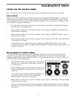
Mixing Signals in 2 Channel Mode
In 2 Channel mode, all mix inputs including MAIN, MASTER INJECT, as well as the Channel AUX input are
summed to a mono signal. In this mode, the individual Channel’s PAN control is used to adjust the balance
between the MAIN( which includes the MASTER INJECT), and the channel AUX input. To design a monitor mix
in the 2 Channel mode follow these steps:
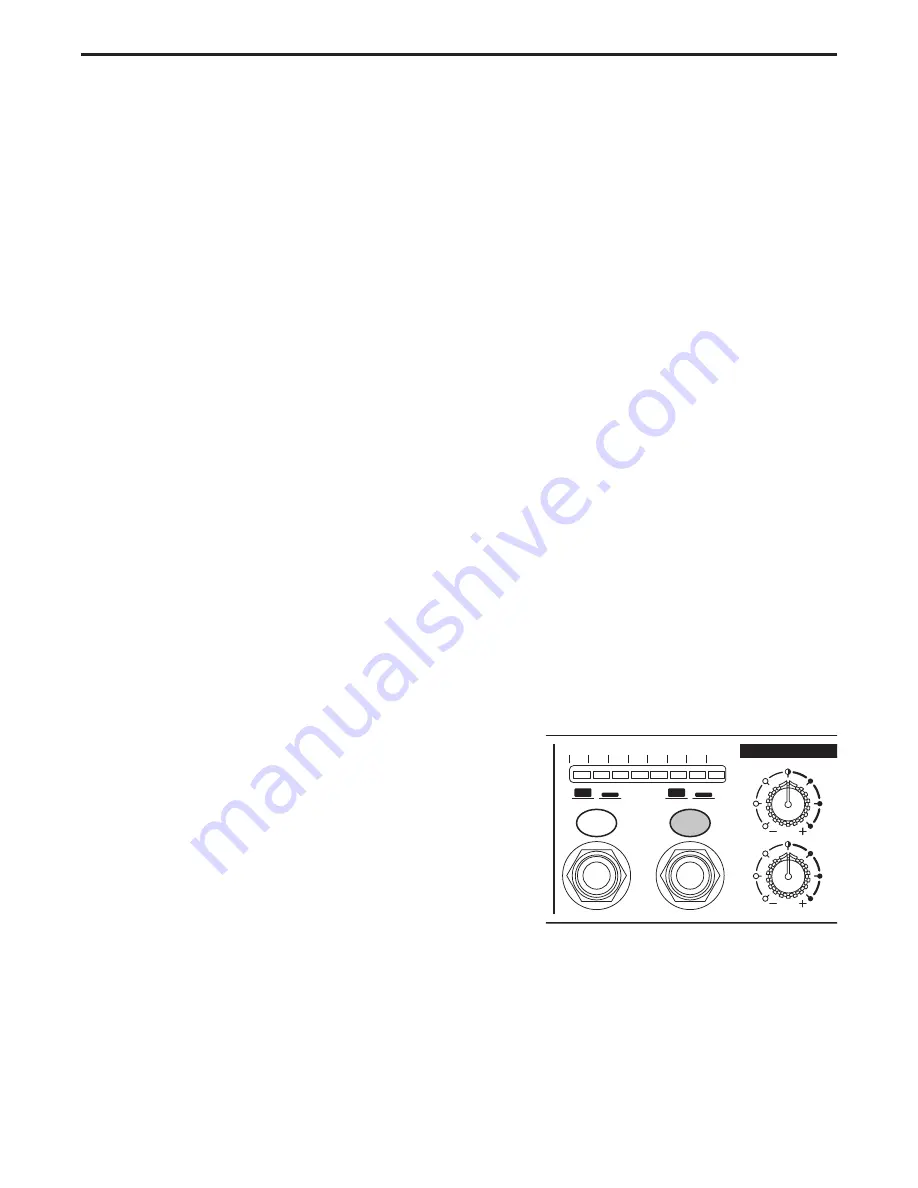
•
Press the ST/2CH switch to the IN positions, you’ll notice the
switch LED is now illuminated indicating that Channel I is in
2- Channel mode.
•
Make a Stereo connection from your mixer’s auxiliary or buss
outputs to the MAIN Left and Right inputs on the S•phone’s
rear panel.
•
If a second mix is desired, make a Stereo connection from
your mixer’s auxiliary or buss outputs to the MASTER
INJECT located on the S•phone’s front panel.
•
Make a Stereo connection from your mixer’s auxiliary or buss outputs to the Channel 1 AUX input located
on the S•phone’s front panel.
•
In the 2-CH mode you adjust the mix balance between the MAIN, MATER INJECT mix and the Channel
AUX input at your mixer by balancing the combinations of auxiliary and bus sends you have connected to
the S•phone.
CHANN
CHANNEL LEVEL dB
-30
-18 -12
-24
-6
-3
CLIP
0
MUTE / ON
ST / 2CH
PHONES
AUX IN
HF
0
12
8
8
4
4
12
LF
12
8
8
4
12
4
N