background image

15

Suggested Performance Application

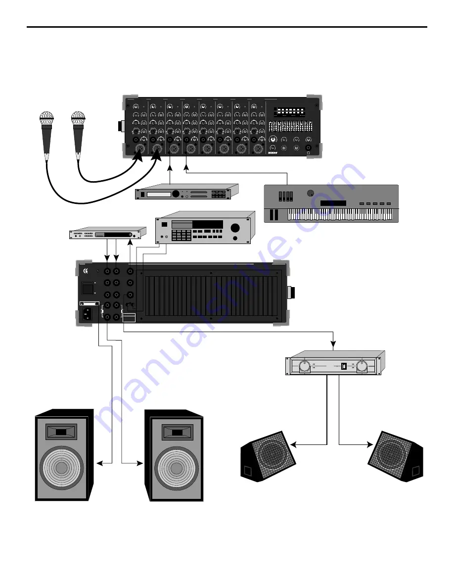
The following illustration shows the basic interconnections between an SD8 and external equipment when used in a
typical live performance application:

The main connections here involve connecting the SD8 speaker outputs to PA speakers and the Monitor output to the
input of an external amplifier driving onstage monitors.  Various microphones and line level signals are connected to
channel mic and line inputs and a CD or tape player is connected to the CD/Tape input.  An external signal processor is
connected to Aux Send 2, with the resulting processed signal returned to Aux Returns 1 and 2.

SIGNAL PROCESSOR

MIDI TONE GENERATOR

  CD OR DAT

MIDI KEYBOARD

MIC 1 MIC 2

LINE

 3

LINE

 4

8 CHANNEL STEREO MIXER 250 WATT AMPLIFIER

-15

-9

-6

-3

0

+3

+6

PHANTOM

POWER

RETURN 1-2

MAIN LEVEL

EFFECT

HEADPHONES

PRESET

MONITOR

PROTECT

AUX1/MON

-15

-9

-6

-3

0

+3

+6

L

R

32Hz

64Hz

125Hz

250Hz

500Hz

1K

2K

4K

8K

16K

+12dB

0dB

-12dB

32Hz

64Hz

125Hz

250Hz

500Hz

1K

2K

4K

8K

16K

SD8 STEREO MIXER AMPLIFIER

SAMSON

MIX

D

S

P  

P

O

W

E

R

E

D

LINE

MIC

PEAK

CHANNEL 8

+10

O

HIGH

+15

O

-15

LEVEL

+10

O

MID

+12

O

-12

LOW

+15

O

-15

L

R

PAN

DSP  AUX2

LINE

MIC

PEAK

CHANNEL 7

+10

O

HIGH

+15

O

-15

LEVEL

+10

O

MID

+12

O

-12

LOW

+15

O

-15

DSP  AUX2

L

R

PAN

AUX1/MON

LINE

MIC

PEAK

CHANNEL 6

+10

O

HIGH

+15

O

-15

LEVEL

+10

O

MID

+12

O

-12

LOW

+15

O

-15

DSP  AUX2

L

R

PAN

AUX1/MON

LINE

MIC

PEAK

CHANNEL 5

+10

O

HIGH

+15

O

-15

LEVEL

+10

O

MID

+12

O

-12

LOW

+15

O

-15

DSP  AUX2

L

R

PAN

AUX1/MON

LINE

MIC

PEAK

CHANNEL 4

+10

O

HIGH

+15

O

-15

LEVEL

+10

O

MID

+12

O

-12

LOW

+15

O

-15

DSP  AUX2

L

R

PAN

AUX1/MON

LINE

MIC

PEAK

CHANNEL 3

+10

O

HIGH

+15

O

-15

LEVEL

+10

O

MID

+12

O

-12

LOW

+15

O

-15

DSP  AUX2

L

R

PAN

AUX1/MON

LINE

MIC

PEAK

CHANNEL 2

+10

O

HIGH

+15

O

-15

LEVEL

+10

O

MID

+12

O

-12

LOW

+15

O

-15

DSP  AUX2

L

R

PAN

AUX1/MON

LINE

MIC

PEAK

CHANNEL 1

+10

O

HIGH

+15

O

-15

LEVEL

+10

O

MID

+12

O

-12

LOW

+15

O

-15

DSP  AUX2

L

R

PAN

AUX1/MON

+10

O

+10

O

10

1

2

3

4

5

6

7

8 9

11

12

13

14

15

16

10

1

2

3

4

5

6

7

8 9

11

12

13

14

15

16

DSP

+10

+10

O

+10

O

TRIM

-6

-50

+14

-20

0

L

I

N

E

M

I C

TRIM

-6

-50

+14

-20

0

L

I

N

E

M

I C

TRIM

-6

-50

+14

-20

0

L

I

N

E

M

I C

TRIM

-6

-50

+14

-20

0

L

I

N

E

M

I C

TRIM

-6

-50

+14

-20

0

L

I

N

E

M

I C

TRIM

-6

-50

+14

-20

0

L

I

N

E

M

I C

TRIM

-6

-50

+14

-20

0

L

I

N

E

M

I C

TRIM

-6

-50

+14

-20

0

L

I

N

E

M

I C

L

SERVO - 240

SAMSON

R

CH7

POWER

CH8

CH7

CAUTION

RISK OF ELECTRIC SHOCK

DO NOT OPEN

!

SERIAL NUMBER

O

ON

OFF

SAMSON

SD8 STEREO MIXER AMPLIFIER

+48V

PHANTOM

POWER

AC INPUT

115V 50/60Hz

SPEAKER OUT

R MINIMUM 4

 L

AMP IN

R (+4dBu 10K

) L

PRE OUT

R (+4dBu <75

) L

AUX RETURN

2 (+4dBu 10K

) 1

AUX SEND 1
(+4dBu <75

)

AUX SEND 2
(+4dBu <75

)

MON OUT

(+4dBu <75

)

TAPE/CD IN

Summary of Contents for SD8

Page 1: ...OWNERS MANUAL P O W E R E D MIXER S D 8...

Page 2: ...elength for Samson Technologies Corp Copyright 1997 Samson Technologies Corp Printed March 1997 Samson Technologies Corp 575 Underhill Blvd P O Box 9031 Syosset NY 11791 9031 Phone 1 800 3 SAMSON 1 80...

Page 3: ...al Suggestions 11 Setting Up and Using the SD8 12 Setting the Correct Gain Structure 13 Suggested Performance Application 15 Grounding Techniques 16 Using Equalization 17 Using The Aux Sends and Retur...

Page 4: ...ons such as churches or conference rooms In these pages we ll begin with an overview of the main SD8 features followed by a guided tour of the front and rear panels Then we ll describe the various inp...

Page 5: ...ignal Independent three band equalization for each channel enabling you to shape the sound of your input signal sources In addition a ten band graphic master equalizer allows you to tune the output of...

Page 6: ...lifier A rear panel preamplifier output allows you to connect the SD8 to external power amplifiers when higher power ratings are required and or when additional amplifier feeds are necessary A built i...

Page 7: ...N AUX1 MON LINE MIC PEAK CHANNEL 5 10 O HIGH 15 O 15 LEVEL 10 O MID 12 O 12 LOW 15 O 15 DSP AUX2 L R PAN AUX1 MON LINE MIC PEAK CHANNEL 4 10 O HIGH 15 O 15 LEVEL 10 O MID 12 O 12 LOW 15 O 15 DSP AUX2...

Page 8: ...ee the Using Aux Sends and Returns section on page 19 of this manual 3 DSP Aux 2 violet This knob allows you to send signal from one or more channels to the SD8 s internal Zoom Digital Signal Processo...

Page 9: ...to the left output and more signal is sent to the right output making the sound appear right of center To route a signal hard left or right place the pan knob either fully counterclockwise or fully c...

Page 10: ...y thump The rightmost LED labeled Power lights steadily green whenever the SD8 is powered on and fades slowly when the unit is powered off 3 Ten Band Graphic Master EQ These sliders allow you to add 1...

Page 11: ...attenuated when fully counterclockwise the signal is attenuated infinitely in other words there is no Monitor signal sent For more information see the Using the Aux Sends and Returns section on page 1...

Page 12: ...ct injection DI box to determine whether or not it requires 48 volts phantom power Samson cannot assume responsibility if you damage a mic or DI box by incorrectly applying phantom power from the SD8...

Page 13: ...on page 8 It is normally used to connect the unit to an external monitor mixer amplifier speaker system so that the performers can receive an onstage monitor mix independent of the house mix See the U...

Page 14: ...el line inputs will accept either balanced or unbalanced connectors The diagram below shows how balanced 1 4 TRS Tip Ring Sleeve connectors should be wired Unbalanced cables use standard 1 4 phone con...

Page 15: ...ection from the tip of the SD8 speaker jack goes to the hot input of your loudspeaker and that the sleeve of the SD8 speaker jack is connected to the ground input of your loudspeaker 3 Next make the s...

Page 16: ...y are sending completely wet processed signal with no dry unprocessed signal mixed in f If condenser microphones are connected to the SD8 turn on the Phantom switch Finally turn on the SD8 s main powe...

Page 17: ...portant to maximize the amount of signal being sent to them via the SD8 Aux sends As with the internal DSP the idea is to drive these devices as hot as possible short of overloading them and then to u...

Page 18: ...EVEL 10 O MID 12 O 12 LOW 15 O 15 DSP AUX2 L R PAN AUX1 MON LINE MIC PEAK CHANNEL 6 10 O HIGH 15 O 15 LEVEL 10 O MID 12 O 12 LOW 15 O 15 DSP AUX2 L R PAN AUX1 MON LINE MIC PEAK CHANNEL 5 10 O HIGH 15...

Page 19: ...mounted audio devices and are experiencing hum or buzz there s a simple test to determine the source of the problem while keeping all devices powered on and connected with audio cabling physically re...

Page 20: ...d The high and low EQ controls employ what is known as a shelving curve where frequencies either above or below the specified area are affected while the mid frequency control employs what is known as...

Page 21: ...m an overloaded input signal The key is to get the signal right in the first place by using correct gain structure and mic placement Although the specific EQ you will apply to a channel signal is very...

Page 22: ...m outboard devices either as a stereo pair or dual monophonically many popular effects processors provide a single mono input but a stereo output Because the SD8 is a stereo device Aux return 1 is aut...

Page 23: ...e DSP wet signal to be added to the overall mix When set to the fully clockwise 10 position the wet signal is boosted by 10 dB Wet signal is returning at unity gain that is with no boost or attenuatio...

Page 24: ...Effect 1 standard is 1 8 seconds specially designed to Larger Effect values increase the reverb time from enhance percussion 0 6 seconds Effect 2 to 3 4 seconds Effect 16 10 Drums a reverb specially A...

Page 25: ...dB Aux Return to Pre Out 10 dB Tape In to Pre Out 14 dB Mic to Aux Send 1 Trim Min Max 20 64 dB Mic to Aux Send 2 Trim Min Max 30 74 dB Mic to Monitor Out Trim Min Max 30 74 dB Residual Noise at Pre O...

Page 26: ...e 3 dB DC 130 kHz 20 50 kHz Signal To Noise Ratio with 30 kHz LPF 112 dB 105 dB Min Residual Noise with 30 kHz LPF 84 dBu 80 dBu Max Idle Current across Emitter Resistor 6 mA 15 mA Max DC Offset Volta...

Reviews: