background image

17

Using Equalization

One of the most exciting aspects to using a mixer such as the SD8 is having the
ability to shape a sound, using a process called equalization.  But there are few
areas of audio engineering more misunderstood than equalization, and, just as
good EQ can really help a sound, bad EQ can really hurt it, so read on...

Every naturally occurring sound consists of a broad range of pitches, or
frequencies, combined together in a unique way.  This blend is what gives every
sound its distinctive tonal color.  The EQ section in a mixer allows you to alter a
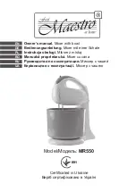
sound by boosting or attenuating specific frequency areas.  The SD8 provides a
ten-band graphic master equalizer (more about this shortly) as well as 
independent three-band equalization for each channel, with center frequency
areas of, from high to low: 10 kHz, 800 Hz, and 80 Hz.  Each channel EQ knob is
labeled with the maximum amount of cut or boost provided (± 15 db in the case
of the high and low frequencies and ± 12 db in the case of the mid frequency).

We provided these particular frequency areas because they have maximum
impact on musical signals—that’s why they are sometimes known as “sweet
spots.”  When an EQ knob is in its center detented position (“0”), it is having no
effect.  When it is moved right of center, the particular frequency area is being
boosted; when it is moved left of center, the frequency area is being attenuated.
The high and low EQ controls employ what is known as a shelving curve (where
frequencies either above or below the specified area are affected) while the mid
frequency control employs what is known as a bell curve (where frequencies
both above and below the specified area are affected).

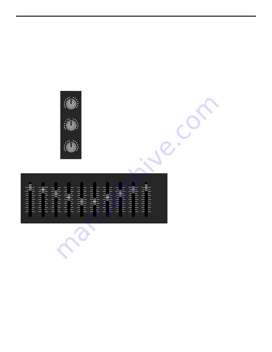
The ten-band graphic master equalizer
affects the overall output signal of the
SD8.  Its main function is to allow you to
“tune” the device to the particular room
environment you are in.  Perhaps its
most important job is to enable you to
eliminate ringing or feedback problems
caused when a microphone is too close
to a loudspeaker.  To accomplish this,
start with all ten bands flat (that is, all
ten sliders at their detented “0” center
position).  Then, one by one, raise each

slider until you hear the feedback or ringing markedly increase.  This allows you
to identify the problematic frequency area (it will most commonly be one or more
of the high mid-range or high frequency areas).  When you’ve located the
problem area(s), it’s simply a matter of lowering that slider or sliders below the
0 point until the ringing or feedback disappears.  Don’t lower the frequency area
any further than you need to, or the quality of the overall sound may suffer.
If you don’t specifically need to utilize the SD8’s ten-band graphic master
equalizer in a particular environment, leave it completely flat (all sliders at their
center detented “0” position).

HIGH

+15

O

-15

MID

+12

O

-12

LOW

+15

O

-15

32Hz

64Hz

125Hz

250Hz

500Hz

1K

2K

4K

8K

16K

+12dB

0dB

-12dB

32Hz

64Hz

125Hz

250Hz

500Hz

1K

2K

4K

8K

16K

Ten-band graphic master equalizer

Summary of Contents for SD8

Page 1: ...OWNERS MANUAL P O W E R E D MIXER S D 8...

Page 2: ...elength for Samson Technologies Corp Copyright 1997 Samson Technologies Corp Printed March 1997 Samson Technologies Corp 575 Underhill Blvd P O Box 9031 Syosset NY 11791 9031 Phone 1 800 3 SAMSON 1 80...

Page 3: ...al Suggestions 11 Setting Up and Using the SD8 12 Setting the Correct Gain Structure 13 Suggested Performance Application 15 Grounding Techniques 16 Using Equalization 17 Using The Aux Sends and Retur...

Page 4: ...ons such as churches or conference rooms In these pages we ll begin with an overview of the main SD8 features followed by a guided tour of the front and rear panels Then we ll describe the various inp...

Page 5: ...ignal Independent three band equalization for each channel enabling you to shape the sound of your input signal sources In addition a ten band graphic master equalizer allows you to tune the output of...

Page 6: ...lifier A rear panel preamplifier output allows you to connect the SD8 to external power amplifiers when higher power ratings are required and or when additional amplifier feeds are necessary A built i...

Page 7: ...N AUX1 MON LINE MIC PEAK CHANNEL 5 10 O HIGH 15 O 15 LEVEL 10 O MID 12 O 12 LOW 15 O 15 DSP AUX2 L R PAN AUX1 MON LINE MIC PEAK CHANNEL 4 10 O HIGH 15 O 15 LEVEL 10 O MID 12 O 12 LOW 15 O 15 DSP AUX2...

Page 8: ...ee the Using Aux Sends and Returns section on page 19 of this manual 3 DSP Aux 2 violet This knob allows you to send signal from one or more channels to the SD8 s internal Zoom Digital Signal Processo...

Page 9: ...to the left output and more signal is sent to the right output making the sound appear right of center To route a signal hard left or right place the pan knob either fully counterclockwise or fully c...

Page 10: ...y thump The rightmost LED labeled Power lights steadily green whenever the SD8 is powered on and fades slowly when the unit is powered off 3 Ten Band Graphic Master EQ These sliders allow you to add 1...

Page 11: ...attenuated when fully counterclockwise the signal is attenuated infinitely in other words there is no Monitor signal sent For more information see the Using the Aux Sends and Returns section on page 1...

Page 12: ...ct injection DI box to determine whether or not it requires 48 volts phantom power Samson cannot assume responsibility if you damage a mic or DI box by incorrectly applying phantom power from the SD8...

Page 13: ...on page 8 It is normally used to connect the unit to an external monitor mixer amplifier speaker system so that the performers can receive an onstage monitor mix independent of the house mix See the U...

Page 14: ...el line inputs will accept either balanced or unbalanced connectors The diagram below shows how balanced 1 4 TRS Tip Ring Sleeve connectors should be wired Unbalanced cables use standard 1 4 phone con...

Page 15: ...ection from the tip of the SD8 speaker jack goes to the hot input of your loudspeaker and that the sleeve of the SD8 speaker jack is connected to the ground input of your loudspeaker 3 Next make the s...

Page 16: ...y are sending completely wet processed signal with no dry unprocessed signal mixed in f If condenser microphones are connected to the SD8 turn on the Phantom switch Finally turn on the SD8 s main powe...

Page 17: ...portant to maximize the amount of signal being sent to them via the SD8 Aux sends As with the internal DSP the idea is to drive these devices as hot as possible short of overloading them and then to u...

Page 18: ...EVEL 10 O MID 12 O 12 LOW 15 O 15 DSP AUX2 L R PAN AUX1 MON LINE MIC PEAK CHANNEL 6 10 O HIGH 15 O 15 LEVEL 10 O MID 12 O 12 LOW 15 O 15 DSP AUX2 L R PAN AUX1 MON LINE MIC PEAK CHANNEL 5 10 O HIGH 15...

Page 19: ...mounted audio devices and are experiencing hum or buzz there s a simple test to determine the source of the problem while keeping all devices powered on and connected with audio cabling physically re...

Page 20: ...d The high and low EQ controls employ what is known as a shelving curve where frequencies either above or below the specified area are affected while the mid frequency control employs what is known as...

Page 21: ...m an overloaded input signal The key is to get the signal right in the first place by using correct gain structure and mic placement Although the specific EQ you will apply to a channel signal is very...

Page 22: ...m outboard devices either as a stereo pair or dual monophonically many popular effects processors provide a single mono input but a stereo output Because the SD8 is a stereo device Aux return 1 is aut...

Page 23: ...e DSP wet signal to be added to the overall mix When set to the fully clockwise 10 position the wet signal is boosted by 10 dB Wet signal is returning at unity gain that is with no boost or attenuatio...

Page 24: ...Effect 1 standard is 1 8 seconds specially designed to Larger Effect values increase the reverb time from enhance percussion 0 6 seconds Effect 2 to 3 4 seconds Effect 16 10 Drums a reverb specially A...

Page 25: ...dB Aux Return to Pre Out 10 dB Tape In to Pre Out 14 dB Mic to Aux Send 1 Trim Min Max 20 64 dB Mic to Aux Send 2 Trim Min Max 30 74 dB Mic to Monitor Out Trim Min Max 30 74 dB Residual Noise at Pre O...

Page 26: ...e 3 dB DC 130 kHz 20 50 kHz Signal To Noise Ratio with 30 kHz LPF 112 dB 105 dB Min Residual Noise with 30 kHz LPF 84 dBu 80 dBu Max Idle Current across Emitter Resistor 6 mA 15 mA Max DC Offset Volta...

Reviews: