background image

20

Using the Internal Digital Signal Processor (DSP)

There’s probably no better way to enhance audio than with the judicious use of effects
such as reverb and echo.  The SD8 has its own built-in Digital Signal Processor (DSP)
chip which provides some of the best effects around.  These are some of the same
effects, in fact, that you’ll find in the highly acclaimed Zoom Studio 1202 signal 
processor.

As discussed in the “Using The Aux Sends and Returns” section on page 19 in this
manual, each SD8 channel has its own discrete DSP/ Aux 2 send knob.  This allows
effects to be applied only to certain signals and not just to the overall mix (applying
effects to the overall mix could make for a muddy sound).  As each channel’s
DSP/ Aux 2 send knob is turned counterclockwise (towards “DSP”), signal from that
channel is routed increasingly to the internal DSP.

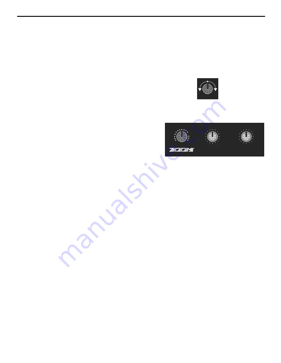
To return signal from the internal DSP, use the DSP Mix Level knob in
the SD8 main section (as described on page 8 of this manual).  When
set to the fully counterclockwise (“

”) position, no signal is returned

from the DSP, so you’ll hear only “dry” signal.  Turning the knob
clockwise will cause more and more DSP (“wet”) signal to be added to
the overall mix.  When set to the fully clockwise (“+10”) position, the
wet signal is boosted by 10 dB.  Wet signal is returning at unity gain
(that is, with no boost or attenuation) when the knob set to the “0”
position.  For best signal-to-noise ratio, you should use the
DSP/ Aux 2 send knobs to drive the DSP as hot as possible (short of
overloading it) and then use the DSP Mix Level knob to carefully set
the amount of processed signal you want to hear.

The SD8 provides 16 preset effect types (selected with the main section Preset knob),
and 16 variations for each preset (selected with the main section Effect knob), making
for a grand total of 256 different reverbs, delays and echoes—all available at the touch
of a knob.  For each Preset, Effect 1 provides a “standard” setting—that is, a variation
that is deemed as being most characteristic of that Preset type.  To quickly audition all
the SD8 Presets, simply leave the Effect knob at “1” and rotate the Preset knob through
its 16 different positions.  For unusual custom effects, change the Effect setting.

The chart on the following page lists each Preset as well as describing the sonic
variation caused by the different Effect settings 

EFFECT

PRESET

MIX

D

S

P


P

O W

E

R

E

D

10

1

2

3

4

5

6

7

8 9

11

12

13

14

15

16

10

1

2

3

4

5

6

7

8 9

11

12

13

14

15

16

DSP

+10

O

DSP  AUX2

Summary of Contents for SD8

Page 1: ...OWNERS MANUAL P O W E R E D MIXER S D 8...

Page 2: ...elength for Samson Technologies Corp Copyright 1997 Samson Technologies Corp Printed March 1997 Samson Technologies Corp 575 Underhill Blvd P O Box 9031 Syosset NY 11791 9031 Phone 1 800 3 SAMSON 1 80...

Page 3: ...al Suggestions 11 Setting Up and Using the SD8 12 Setting the Correct Gain Structure 13 Suggested Performance Application 15 Grounding Techniques 16 Using Equalization 17 Using The Aux Sends and Retur...

Page 4: ...ons such as churches or conference rooms In these pages we ll begin with an overview of the main SD8 features followed by a guided tour of the front and rear panels Then we ll describe the various inp...

Page 5: ...ignal Independent three band equalization for each channel enabling you to shape the sound of your input signal sources In addition a ten band graphic master equalizer allows you to tune the output of...

Page 6: ...lifier A rear panel preamplifier output allows you to connect the SD8 to external power amplifiers when higher power ratings are required and or when additional amplifier feeds are necessary A built i...

Page 7: ...N AUX1 MON LINE MIC PEAK CHANNEL 5 10 O HIGH 15 O 15 LEVEL 10 O MID 12 O 12 LOW 15 O 15 DSP AUX2 L R PAN AUX1 MON LINE MIC PEAK CHANNEL 4 10 O HIGH 15 O 15 LEVEL 10 O MID 12 O 12 LOW 15 O 15 DSP AUX2...

Page 8: ...ee the Using Aux Sends and Returns section on page 19 of this manual 3 DSP Aux 2 violet This knob allows you to send signal from one or more channels to the SD8 s internal Zoom Digital Signal Processo...

Page 9: ...to the left output and more signal is sent to the right output making the sound appear right of center To route a signal hard left or right place the pan knob either fully counterclockwise or fully c...

Page 10: ...y thump The rightmost LED labeled Power lights steadily green whenever the SD8 is powered on and fades slowly when the unit is powered off 3 Ten Band Graphic Master EQ These sliders allow you to add 1...

Page 11: ...attenuated when fully counterclockwise the signal is attenuated infinitely in other words there is no Monitor signal sent For more information see the Using the Aux Sends and Returns section on page 1...

Page 12: ...ct injection DI box to determine whether or not it requires 48 volts phantom power Samson cannot assume responsibility if you damage a mic or DI box by incorrectly applying phantom power from the SD8...

Page 13: ...on page 8 It is normally used to connect the unit to an external monitor mixer amplifier speaker system so that the performers can receive an onstage monitor mix independent of the house mix See the U...

Page 14: ...el line inputs will accept either balanced or unbalanced connectors The diagram below shows how balanced 1 4 TRS Tip Ring Sleeve connectors should be wired Unbalanced cables use standard 1 4 phone con...

Page 15: ...ection from the tip of the SD8 speaker jack goes to the hot input of your loudspeaker and that the sleeve of the SD8 speaker jack is connected to the ground input of your loudspeaker 3 Next make the s...

Page 16: ...y are sending completely wet processed signal with no dry unprocessed signal mixed in f If condenser microphones are connected to the SD8 turn on the Phantom switch Finally turn on the SD8 s main powe...

Page 17: ...portant to maximize the amount of signal being sent to them via the SD8 Aux sends As with the internal DSP the idea is to drive these devices as hot as possible short of overloading them and then to u...

Page 18: ...EVEL 10 O MID 12 O 12 LOW 15 O 15 DSP AUX2 L R PAN AUX1 MON LINE MIC PEAK CHANNEL 6 10 O HIGH 15 O 15 LEVEL 10 O MID 12 O 12 LOW 15 O 15 DSP AUX2 L R PAN AUX1 MON LINE MIC PEAK CHANNEL 5 10 O HIGH 15...

Page 19: ...mounted audio devices and are experiencing hum or buzz there s a simple test to determine the source of the problem while keeping all devices powered on and connected with audio cabling physically re...

Page 20: ...d The high and low EQ controls employ what is known as a shelving curve where frequencies either above or below the specified area are affected while the mid frequency control employs what is known as...

Page 21: ...m an overloaded input signal The key is to get the signal right in the first place by using correct gain structure and mic placement Although the specific EQ you will apply to a channel signal is very...

Page 22: ...m outboard devices either as a stereo pair or dual monophonically many popular effects processors provide a single mono input but a stereo output Because the SD8 is a stereo device Aux return 1 is aut...

Page 23: ...e DSP wet signal to be added to the overall mix When set to the fully clockwise 10 position the wet signal is boosted by 10 dB Wet signal is returning at unity gain that is with no boost or attenuatio...

Page 24: ...Effect 1 standard is 1 8 seconds specially designed to Larger Effect values increase the reverb time from enhance percussion 0 6 seconds Effect 2 to 3 4 seconds Effect 16 10 Drums a reverb specially A...

Page 25: ...dB Aux Return to Pre Out 10 dB Tape In to Pre Out 14 dB Mic to Aux Send 1 Trim Min Max 20 64 dB Mic to Aux Send 2 Trim Min Max 30 74 dB Mic to Monitor Out Trim Min Max 30 74 dB Residual Noise at Pre O...

Page 26: ...e 3 dB DC 130 kHz 20 50 kHz Signal To Noise Ratio with 30 kHz LPF 112 dB 105 dB Min Residual Noise with 30 kHz LPF 84 dBu 80 dBu Max Idle Current across Emitter Resistor 6 mA 15 mA Max DC Offset Volta...

Reviews: