background image

Guided Tour - Channel

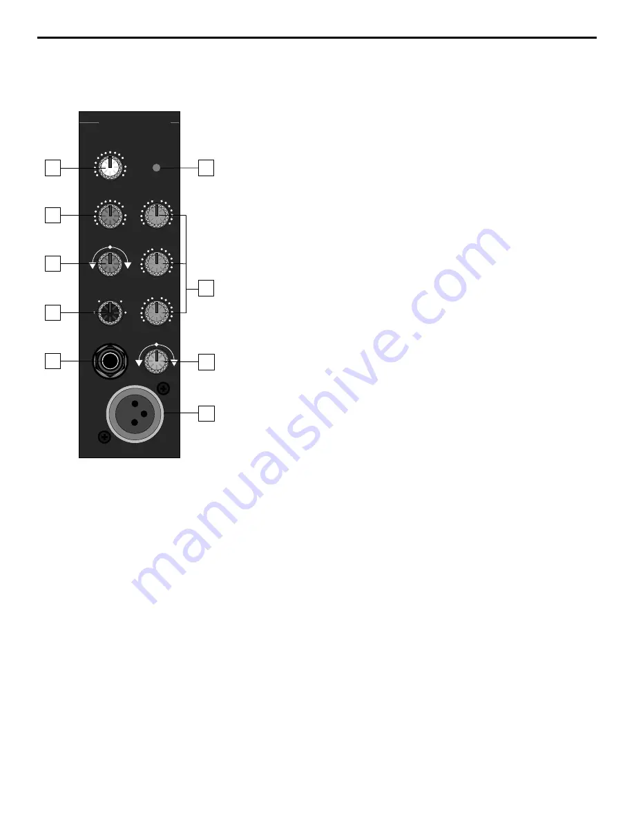
1:  Level (white) - This knob determines the final signal level being sent by a
channel to the main speaker outputs.  In practice, this will be used to adjust the
levels of the various signals being blended together by the SD8.  The “0”
position indicates unity gain (no level attenuation or boost).  Turning the Level
control clockwise from the “0” position (towards the “10” position) causes the
signal to be boosted by as much as 10 dB.  Turning it counterclockwise from “0”
(towards the “

” position) causes the signal to be attenuated (when fully

counterclockwise, the signal is attenuated infinitely—in other words, there is
no sound).  For best signal-to-noise ratio, all channel level controls should be
kept at or near the 0 level.

2:  Aux 1 / Monitor (violet) - This knob allows you to send signal from one or
more channels to the SD8’s monophonic Monitor output or to an external device
connected to the Aux Send 1 output jack on the rear panel.  This send is
pre-fade; that is, the level of the signal is determined solely by the channel’s
input Trim (see #4 below), and is unaffected by its EQ settings and the position
of its Level control.  At the “0” position, the signal is routed with unity gain (that
is, no boost or attenuation).  As each Aux 1 / Monitor knob is turned clockwise
from the “0” position (towards the “10” position), the signal is boosted by as
much as 10 dB; as it is turned counterclockwise from the 0 position (towards
the “

” position), the signal is attenuated.  When turned fully counterclockwise,

the signal is attenuated infinitely—in other words, no signal is routed.  For more
information, see the “Using Aux Sends and Returns” section on page 19 of this
manual.

3:  DSP / Aux 2 (violet) - This knob allows you to send signal from one or more
channels to the SD8’s internal Zoom Digital Signal Processor (DSP) or to an
external device connected to the Aux Send 2 output jack on the rear panel.
This effects send is post-fade; that is, the level of the signal is determined by
the channel’s input Trim (see #4 below), its EQ settings (see #6 below), and the
position of its Level control.  At the 12 o’clock position, there is no signal routed.

As the DSP / Aux 2 knob is turned clockwise (towards “Aux 2”), signal is routed
increasingly to Aux Send 2.  As the DSP / Aux 2 knob is turned counterclock-
wise (towards “DSP”), signal is routed increasingly to the internal Zoom Digital
Signal Processor.  For more information, see the “Using Aux Sends and
Returns” section on page 19 of this manual and the “Using the Internal DSP”
section on page 20 of this manual.

4:  Trim (black) - This knob allows you to set the input gain of the connected
mic or line signal over an exceptionally wide range.  Continuously adjustable
from -6 dB to -50 dB, the input gain is raised when the Trim knob is turned
clockwise and attenuated when it is turned counterclockwise.  For information
on how to use this, see the “Setting The Correct Gain Structure” on page 13 in
this manual.

5:  Peak LED (red) - This warning light indicates an overload situation.  It lights
whenever a channel’s signal is 5 dB short of clipping.  To stop it from lighting
(and to eliminate the accompanying sonic distortion), turn down the channel’s
input Trim knob (see #4 above) or reduce the amount of equalization boost (see
#6 on the next page).

5

5

LINE

MIC

PEAK

CHANNEL 1

+10

O

HIGH

+15

O

-15

LEVEL

+10

O

MID

+12

O

-12

-6

-50

TRIM

-20

LOW

+15

O

-15

DSP  AUX2

L

R

PAN

AUX1/MON

1

2

3

4

6

8

7

9

Summary of Contents for SD8

Page 1: ...OWNERS MANUAL P O W E R E D MIXER S D 8...

Page 2: ...elength for Samson Technologies Corp Copyright 1997 Samson Technologies Corp Printed March 1997 Samson Technologies Corp 575 Underhill Blvd P O Box 9031 Syosset NY 11791 9031 Phone 1 800 3 SAMSON 1 80...

Page 3: ...al Suggestions 11 Setting Up and Using the SD8 12 Setting the Correct Gain Structure 13 Suggested Performance Application 15 Grounding Techniques 16 Using Equalization 17 Using The Aux Sends and Retur...

Page 4: ...ons such as churches or conference rooms In these pages we ll begin with an overview of the main SD8 features followed by a guided tour of the front and rear panels Then we ll describe the various inp...

Page 5: ...ignal Independent three band equalization for each channel enabling you to shape the sound of your input signal sources In addition a ten band graphic master equalizer allows you to tune the output of...

Page 6: ...lifier A rear panel preamplifier output allows you to connect the SD8 to external power amplifiers when higher power ratings are required and or when additional amplifier feeds are necessary A built i...

Page 7: ...N AUX1 MON LINE MIC PEAK CHANNEL 5 10 O HIGH 15 O 15 LEVEL 10 O MID 12 O 12 LOW 15 O 15 DSP AUX2 L R PAN AUX1 MON LINE MIC PEAK CHANNEL 4 10 O HIGH 15 O 15 LEVEL 10 O MID 12 O 12 LOW 15 O 15 DSP AUX2...

Page 8: ...ee the Using Aux Sends and Returns section on page 19 of this manual 3 DSP Aux 2 violet This knob allows you to send signal from one or more channels to the SD8 s internal Zoom Digital Signal Processo...

Page 9: ...to the left output and more signal is sent to the right output making the sound appear right of center To route a signal hard left or right place the pan knob either fully counterclockwise or fully c...

Page 10: ...y thump The rightmost LED labeled Power lights steadily green whenever the SD8 is powered on and fades slowly when the unit is powered off 3 Ten Band Graphic Master EQ These sliders allow you to add 1...

Page 11: ...attenuated when fully counterclockwise the signal is attenuated infinitely in other words there is no Monitor signal sent For more information see the Using the Aux Sends and Returns section on page 1...

Page 12: ...ct injection DI box to determine whether or not it requires 48 volts phantom power Samson cannot assume responsibility if you damage a mic or DI box by incorrectly applying phantom power from the SD8...

Page 13: ...on page 8 It is normally used to connect the unit to an external monitor mixer amplifier speaker system so that the performers can receive an onstage monitor mix independent of the house mix See the U...

Page 14: ...el line inputs will accept either balanced or unbalanced connectors The diagram below shows how balanced 1 4 TRS Tip Ring Sleeve connectors should be wired Unbalanced cables use standard 1 4 phone con...

Page 15: ...ection from the tip of the SD8 speaker jack goes to the hot input of your loudspeaker and that the sleeve of the SD8 speaker jack is connected to the ground input of your loudspeaker 3 Next make the s...

Page 16: ...y are sending completely wet processed signal with no dry unprocessed signal mixed in f If condenser microphones are connected to the SD8 turn on the Phantom switch Finally turn on the SD8 s main powe...

Page 17: ...portant to maximize the amount of signal being sent to them via the SD8 Aux sends As with the internal DSP the idea is to drive these devices as hot as possible short of overloading them and then to u...

Page 18: ...EVEL 10 O MID 12 O 12 LOW 15 O 15 DSP AUX2 L R PAN AUX1 MON LINE MIC PEAK CHANNEL 6 10 O HIGH 15 O 15 LEVEL 10 O MID 12 O 12 LOW 15 O 15 DSP AUX2 L R PAN AUX1 MON LINE MIC PEAK CHANNEL 5 10 O HIGH 15...

Page 19: ...mounted audio devices and are experiencing hum or buzz there s a simple test to determine the source of the problem while keeping all devices powered on and connected with audio cabling physically re...

Page 20: ...d The high and low EQ controls employ what is known as a shelving curve where frequencies either above or below the specified area are affected while the mid frequency control employs what is known as...

Page 21: ...m an overloaded input signal The key is to get the signal right in the first place by using correct gain structure and mic placement Although the specific EQ you will apply to a channel signal is very...

Page 22: ...m outboard devices either as a stereo pair or dual monophonically many popular effects processors provide a single mono input but a stereo output Because the SD8 is a stereo device Aux return 1 is aut...

Page 23: ...e DSP wet signal to be added to the overall mix When set to the fully clockwise 10 position the wet signal is boosted by 10 dB Wet signal is returning at unity gain that is with no boost or attenuatio...

Page 24: ...Effect 1 standard is 1 8 seconds specially designed to Larger Effect values increase the reverb time from enhance percussion 0 6 seconds Effect 2 to 3 4 seconds Effect 16 10 Drums a reverb specially A...

Page 25: ...dB Aux Return to Pre Out 10 dB Tape In to Pre Out 14 dB Mic to Aux Send 1 Trim Min Max 20 64 dB Mic to Aux Send 2 Trim Min Max 30 74 dB Mic to Monitor Out Trim Min Max 30 74 dB Residual Noise at Pre O...

Page 26: ...e 3 dB DC 130 kHz 20 50 kHz Signal To Noise Ratio with 30 kHz LPF 112 dB 105 dB Min Residual Noise with 30 kHz LPF 84 dBu 80 dBu Max Idle Current across Emitter Resistor 6 mA 15 mA Max DC Offset Volta...

Reviews: