background image

17

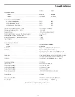
Specifications


SZ240 

SZ480

All channels driven
    8 ohms  . . . . . . . . . . . . . . . . . . . . . . . . . . . . . . . . . . . . . . . . . . . . . . . . . . . . . . . .65 Watts 

65 Watts

    4 ohms  . . . . . . . . . . . . . . . . . . . . . . . . . . . . . . . . . . . . . . . . . . . . . . . . . . . . . . . .120 Watts 

120 Watts

Current Consumption(115VAC)
   @1/8 rated power 4ohms . . . . . . . . . . . . . . . . . . . . . . . . . . . . . . . . . . . . . . . .0.3A 

0.6A

   @1/3 rated power 4ohms . . . . . . . . . . . . . . . . . . . . . . . . . . . . . . . . . . . . . . . .0.8A 

1.6A

   @ rated power 4ohms, max. . . . . . . . . . . . . . . . . . . . . . . . . . . . . . . . . . . . . .2.5A  

5.0A

Input Sensitivity (Balanced Line Input) . . . . . . . . . . . . . . . . . . . . . . . . . . . . . . .1.0 + 0.2Vrms / 10Kohm
Frequency Response (50Hz~18kHz)  . . . . . . . . . . . . . . . . . . . . . . . . . . . . . . . . . +1.5/-3dB
Dynamic Range . . . . . . . . . . . . . . . . . . . . . . . . . . . . . . . . . . . . . . . . . . . . . . . . . . . . . >90 dB A-weighted, typical
THD+N (AES17 20kHz brickwall filter, Rated output) . . . . . . . . . . . . . . . . . .Less than 5%
S/N Ratio (AES17 20kHz brickwall filter) . . . . . . . . . . . . . . . . . . . . . . . . . . . . . .90dB
Residual Noise (AES17 20kHz brickwall filter) . . . . . . . . . . . . . . . . . . . . . . . . .-70dB
Input Clipping . . . . . . . . . . . . . . . . . . . . . . . . . . . . . . . . . . . . . . . . . . . . . . . . . . . . . .+22dBu

Connectors (each channel)
    Input: . . . . . . . . . . . . . . . . . . . . . . . . . . . . . . . . . . . . . . . . . . . . . . . . . . . . . . . . . . .Active balanced Euroblock
  Output:  . . . . . . . . . . . . . . . . . . . . . . . . . . . . . . . . . . . . . . . . . . . . . . . . . . . . . . . . .Euroblock
Controls  . . . . . . . . . . . . . . . . . . . . . . . . . . . . . . . . . . . . . . . . . . . . . . . . . . . . . . . . . . . .AC power switch,Channel volume, Limiter
Indicators . . . . . . . . . . . . . . . . . . . . . . . . . . . . . . . . . . . . . . . . . . . . . . . . . . . . . . . . . . .Power on(blue),Protection(amber)
       . . . . . . . . . . . . . . . . . . . . . . . . . . . . . . . . . . . . . . . . . . . . . . . . . . . . . . . . . . . . . . .Signal(green) for each Ch.,Peak(red) for each Ch.

Protection . . . . . . . . . . . . . . . . . . . . . . . . . . . . . . . . . . . . . . . . . . . . . . . . . . . . . . . . . . Short circuit,Thermal,Current limit,DC offset,Current 

inrush,RF protection, Turn on/Turn off muting

Cooling . . . . . . . . . . . . . . . . . . . . . . . . . . . . . . . . . . . . . . . . . . . . . . . . . . . . . . . . . . . . .Continuously variable speed, fan forced air

Transformer Rating . . . . . . . . . . . . . . . . . . . . . . . . . . . . . . . . . . . . . . . . . . . . . . . . . .120 Watts 
Input voltage . . . . . . . . . . . . . . . . . . . . . . . . . . . . . . . . . . . . . . . . . . . . . . . . . . . . . . .28.28 Vrms 100 watts / 8_
Output Tap 1: Voltage . . . . . . . . . . . . . . . . . . . . . . . . . . . . . . . . . . . . . . . . . . . . . . .70.7 Vrms 50_ load
Output Tap 2: Voltage . . . . . . . . . . . . . . . . . . . . . . . . . . . . . . . . . . . . . . . . . . . . . . .100 Vrms 100_ load
Output Tap 3: Voltage . . . . . . . . . . . . . . . . . . . . . . . . . . . . . . . . . . . . . . . . . . . . . . .20 Vrms 4_ load
Power Requirements . . . . . . . . . . . . . . . . . . . . . . . . . . . . . . . . . . . . . . . . . . . . . . . . 100/115/220/230/240 VAC, 50/60 Hz

Construction  . . . . . . . . . . . . . . . . . . . . . . . . . . . . . . . . . . . . . . . . . . . . . . . . . . . . . . .All Steel

Dimensions(WXHXD)  . . . . . . . . . . . . . . . . . . . . . . . . . . . . . . . . . . . . . . . . . . . . . . .19”(483mm)X3.5”(89mm)X16”(408mm)
 Net  Weight  . . . . . . . . . . . . . . . . . . . . . . . . . . . . . . . . . . . . . . . . . . . . . . . . . . . . . . . .322.5lb.(10.2kg)  

32lb.(14.5kg) 

Specifications are subject to change without notice.

Summary of Contents for SZ240

Page 1: ...SZ240 SZ480 POWER AMPLIFERS SZ SERIES...

Page 2: ...NG TYPE PLUG POLARIZED PLUG HAS TWO BLADES WITH ONE WIDER THAN THE OTHER GROUNDING TYPE PLUG HAS TWO BLADES AND A THIRD GROUNDING PRONG 4HE WIDE BLADE OR THE THIRD PRONG ARE PROVIDED FOR YOUR SAFETY F...

Page 3: ...or objects have fallen into the unit the unit has been exposed to rain or moisture does not operate normally or has been dropped PRECAUCION Para reducir el riesgo de incendios o descargas no permita q...

Page 4: ...Z Series Features 2 SZ480 Layout Front Panel 3 SZ480 Layout Rear Panel 4 SZ240 Layout Front Panel 5 SZ240 Layout Rear Panel 6 Designing an Installation Plan 7 Setting Up and Using Your SZ Series 10 Th...

Page 5: ...ch rack mount design and convenient carry handles facilitating easy installation in any rack Optimized for commercial installations houses of worship live sound venues and for driving small and medium...

Page 6: ...B crosstalk of 80 dB and frequency response of 10 Hz to 25 kHz guarantee ultra clean sound quality LED signal indicators for each channel continuously display power output levels and allow you to corr...

Page 7: ...f When lit no signal is provided to any connected speakers thus muting them and preventing any thump from occurring For a complete description of the conditions under which this light goes on see the...

Page 8: ...terconnection instructions 3 Limiter Each amplifier channel has a quick attack Limiter with peak detection to help ensure a clean signal The Limiter for each individual channel can be set to on or off...

Page 9: ...s whenever the channel is outputting signal at full strength For the best signal to noise ratio the right PEAK segment should light occasionally during peak levels if it lights frequently you may be o...

Page 10: ...nterconnection instructions 3 Limiter Each amplifier channel has a quick attack Limiter with peak detection to help ensure a clean signal The Limiter for each individual channel can be set to on or of...

Page 11: ...onnect line level signals on all four input channels so signals from TAPE CD DVD or Karaoke players Audio Video TV monitors Radio Tuners DJ mixers or any other line level device can be used as a sound...

Page 12: ...some time to consider where you need to have sound in your particular installation After you have decided where you need to create sound zones you can consider your speaker selection but first decide...

Page 13: ...iers have built in transformers on each channel that step up the output voltage and reduce the current allowing you to connect to a series of speakers with step down transformers over long cable runs...

Page 14: ...xt make the signal input connections using the Euroblock input connectors on the rear panel If your mixer has balanced outputs we recommend the use of three conductor cabling and connectors unbalanced...

Page 15: ...s and that both the front and rear panels are unobstructed Severe over current conditions This occurs whenever the signal being input to the SZ Series rises to a level above 20 THD Total Harmonic Dist...

Page 16: ...and 70 Volt operation SZ Series Connections 8 Ohm Operation One 8 Ohm speaker per amplifer 8 Ohm 8 Ohm 8 Ohm 8 Ohm 4 Ohm 4 Ohm 4 Ohm 4 Ohm 4 Ohm Operation Two 8 Ohm speakers per amplifer 70 Volt Opera...

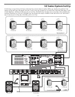
Page 17: ...first two SZ amp channels are connected to four wall mounted speakers in each of the Dining Rooms with their transformers set to a 25 watt tap The third SZ amp channel powers two speakers in the outs...

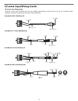
Page 18: ...ways to interface the SZ series amplifers depending on your exact system set up Follow the cable diagrams below for connecting to the input of your amplifier Euroblock to RCA Unbalanced Euroblock to 1...

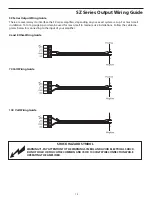
Page 19: ...e zip cord can be used for most small to medium size installations Follow the cable dia grams below for connecting to the input of your amplifier 4 and 8 Ohm Wiring Guide 70 Volt Wiring Guide 100 Volt...

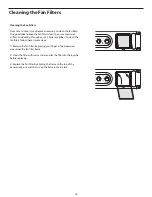
Page 20: ...d cooling through your SZ Series amplifier To clean the fan filters follow these simple steps 1 Remove the fan filter by placing your finger in the depressed area under the fan filter frame 2 Clean th...

Page 21: ...channel Input Active balanced Euroblock Output Euroblock Controls AC power switch Channel volume Limiter Indicators Power on blue Protection amber Signal green for each Ch Peak red for each Ch Protect...

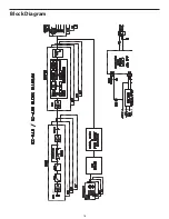
Page 22: ...18 Block Diagram...

Page 23: ......

Page 24: ...Samson Technologies Corp 45 Gilpin Avenue Hauppauge New York 11788 8816 Phone 1 800 3 SAMSON 1 800 372 6766 Fax 631 784 2201 www samsontech com...

Reviews: