EB 8384-1 EN
33
Attachment to the control valve – Mounting parts and accessories
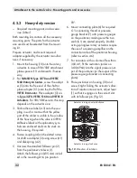
90°.
6.
Mount connecting plate (6) for required
G ¼ connecting thread or pressure
gauge bracket (7) with pressure gauges
on the positioner, making sure the two
seals (6.1) are seated properly. Double-
acting springless rotary actuators require
the use of a reversing amplifier on the
connection side of the positioner housing
(refer to section 4.6).
7. For actuators with a volume of less than
300 cm³, fit the restriction (order no.
1400-6964) into the signal pressure out-
put of the positioner (or the output of the
pressure gauge bracket or connecting
plate).
8.
Place positioner on housing (10) and
screw it tight. Taking the actuator's direc-
tion of rotation into account, adjust lever
(1) so that it engages in the correct slot
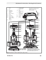
with its follower pin (Fig. 12).
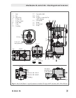
Actuator turning counterclockwise
Actuator turning clockwise
1
10
4
Fig. 12:
Direction of rotation
6
6.1
7
8
1
1.1
1.2
2
4.1
3
10.1
10
11
5
4.3
4
4.2
4.1
3
5.1
5
10.1
10
4.3
4
4.2
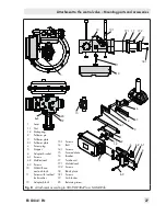
1
Lever
1.1
Nut
1.2
Disk spring
2
Follower pin
3
Adapter
4
Stem connector
4.1
Screw
4.2
Disk spring
4.3
Adhesive label
5
Actuator shaft or
adapter
5.1
Adapter
6
Connecting plate
(only for G ¼)
6.1
Seals
7
Pressure gauge
bracket
8
Pressure gauge
mounting kit
10
Adapter housing
10.1
Screws
11
Spacer
SAMSON Type 3278
VETEC S160, VETEC R
Attachment to rotary actuators acc. to
VDI/VDE 3845 (Sept. 2010), fixing level 1,
AA1 to AA4 size (see section 11.1)
Fit restriction into signal pressure
output for actuators with
<300 cm³ volume
Fig. 13:
Attachment to rotary actuators (heavy-duty version)
Summary of Contents for TROVIS 3730-1
Page 64: ...64 EB 8384 1 EN...
Page 65: ...EB 8384 1 EN 65...
Page 66: ...66 EB 8384 1 EN...
Page 67: ...EB 8384 1 EN 67...
Page 68: ...68 EB 8384 1 EN...
Page 69: ...EB 8384 1 EN 69...
Page 70: ...70 EB 8384 1 EN...
Page 71: ...EB 8384 1 EN 71...
Page 72: ...72 EB 8384 1 EN...
Page 73: ...EB 8384 1 EN 73...
Page 74: ...74 EB 8384 1 EN...
Page 75: ...EB 8384 1 EN 75...

