136
EB 8384-6S EN
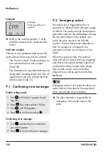
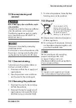
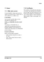
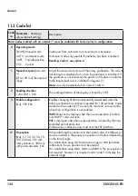
Annex
Code
no.
Parameter
– Readings/
values [default setting]
Description
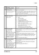
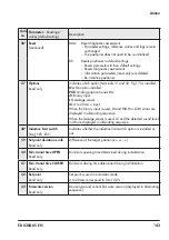
6* Initialization mode
(init mode)
(continued)
KP:
Fine tuning of the input filter · The valve moves through its
entire valve range.
NP:
Zero calibration · The zero point is recalibrated.
NOTICE
Valve will temporarily be moved from its
operating point to CLOSED position.
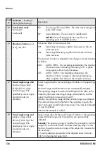
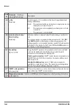
7* Direction of action
(w/x)
[
ää
],
äæ
, ESC
Set point's effect on the valve position
ää
:
Increasing/increasing: a globe valve opens as the set
point increases.
äæ
:
Increasing/decreasing: a globe valve closes as the set
point increases.
The direction of action is adapted to the change in closed direction
as follows:
ATO:
AIR TO OPEN · On completing initialization, the direction
of action remains increasing/increasing (
ää
). A globe
valve opens as the set point increases.
ATC:
AIR TO CLOSE · On completing initialization, the
direction of action changes to increasing/decreasing
(
äæ
). A globe valve closes as the set point increases.
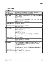
8*
Travel/angle range start
(lower x-range value)
[0.0] to 80.0 % of the
nominal range, ESC
Specified in mm or angle °
provided Code 4 is
activated.
Lower range value for the travel/angle of rotation in the operating
range.
Nominal range and characteristic are automatically adapted.
The operating range is the actual travel/angle of the valve and is
limited by the lower travel/angle range value (Code 8) and the
upper travel/angle range value (Code 9).
Usually, the operating range and the nominal range are identical.
The nominal range can be limited to the operating range by the
lower and upper travel/angle range values. The value is displayed
or must be entered.
See also the example in Code 9.
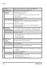
9* Travel/angle range end
(upper x-range value)
20.0 to [100.0 %] of the
nominal range, ESC
Specified in mm or angle °
provided Code 4 is
activated.
Upper range value for the travel/angle of rotation in the operating
range. Nominal range and characteristic are automatically
adapted.
Example:
The operating range is modified, for example to limit the
range of a control valve which has been sized too large. For this
function, the entire resolution range of the set point is converted to
the new limits.
0 % on the display corresponds to the adjusted lower limit and
100 % to the adjusted upper limit.
Summary of Contents for TROVIS SAFE 3730-6
Page 12: ...12 EB 8384 6S EN...
Page 16: ...16 EB 8384 6S EN...
Page 22: ...22 EB 8384 6S EN...
Page 40: ...40 EB 8384 6S EN...
Page 42: ...42 EB 8384 6S EN...
Page 82: ...82 EB 8384 6S EN...
Page 90: ...90 EB 8384 6S EN...
Page 96: ...96 EB 8384 6S EN...
Page 132: ...132 EB 8384 6S EN...
Page 152: ...152 EB 8384 6S EN...
Page 155: ...EB 8384 6S EN 155...
Page 156: ...156 EB 8384 6S EN...
Page 157: ...EB 8384 6S EN 157...
Page 158: ...158 EB 8384 6S EN...
Page 159: ...EB 8384 6S EN 159...
Page 160: ...160 EB 8384 6S EN...
Page 161: ...EB 8384 6S EN 161...
Page 162: ...162 EB 8384 6S EN...
Page 163: ...EB 8384 6S EN 163...
Page 164: ...164 EB 8384 6S EN...
Page 165: ...EB 8384 6S EN 165...
Page 166: ...166 EB 8384 6S EN...
Page 167: ...EB 8384 6S EN 167...
Page 182: ...182 EB 8384 6S EN...
Page 183: ...EB 8384 6S EN 183...

