18
EB 8384-6S EN
Design and principle of operation
The positioner is fitted with three binary con
-
tacts as standard: A fault alarm output indi-
cates a fault to the control room and two
configurable software limit switches are used
to indicate the end positions of the valve.
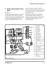
The valve position (x) is transmitted as a
either an angle of rotation or travel to the
pick-up lever and to the travel sensor (2) and
supplied to an analog PD controller. An A/D
converter (4) transmits the position of the
valve to the microcontroller (5). The PD
controller (3) compares this actual position to
the 4 to 20 mA DC control signal (set point)
after it has been converted by the A/D
converter (4). In case of a set point
deviation, the activation of the i/p converter
(6) is changed so that the actuator of the
control valve (1) is pressurized or vented
accordingly over the downstream booster
(7). As a result, the closure member of the
valve (e.g. plug) is moved to the position
determined by the set point (w).
The supply air is supplied to the booster (7)
and the pressure regulator (8). An intermedi-
ate flow regulator (9) with fixed settings is
used to purge the positioner and, at the
same time, guarantees trouble-free operation
of the booster. The output signal pressure
supplied by the booster can be limited by
software. Both pressure sensors (23 and 24)
monitor the supply pressure p
s
and the signal
pressure p
out
.
The volume restriction Q (10) is used to opti-
mize the positioner.
3.1 Safety function (SIL)
The safety function is based on the shutdown
of the i/p converter (6). This causes the
pneumatic actuator to be vented and the
valve to move to its fail-safe position.
Monitoring of the input signal
The i/p converter is switched off when the
input signal of the positioner at terminals
+11/–12 falls below 3.8 mA or 4.4 mA de
-
pending on the positioner version (a signal
range of 4 to 20 mA is required). See Fig. 1.
Monitoring the voltage supply
(version with forced venting
and
solenoid
valve
The i/p converter and the solenoid valve
(when installed) are shut down whenever the
voltage at ter81/–82 falls below
12 V (an input voltage of 24 V DC is re
-
quired). See Fig. 1.
When the i/p converter is switched off as
part of the monitoring of the input signal or
the voltage supply, the fail-safe position
S
is
activated and is indicated on the positioner
display.
If required, the user can check the safety
function using the software.
Details on EXPERTplus Valve Diagnostics in
the Operating Instructions
u
Summary of Contents for TROVIS SAFE 3730-6
Page 12: ...12 EB 8384 6S EN...
Page 16: ...16 EB 8384 6S EN...
Page 22: ...22 EB 8384 6S EN...
Page 40: ...40 EB 8384 6S EN...
Page 42: ...42 EB 8384 6S EN...
Page 82: ...82 EB 8384 6S EN...
Page 90: ...90 EB 8384 6S EN...
Page 96: ...96 EB 8384 6S EN...
Page 132: ...132 EB 8384 6S EN...
Page 152: ...152 EB 8384 6S EN...
Page 155: ...EB 8384 6S EN 155...
Page 156: ...156 EB 8384 6S EN...
Page 157: ...EB 8384 6S EN 157...
Page 158: ...158 EB 8384 6S EN...
Page 159: ...EB 8384 6S EN 159...
Page 160: ...160 EB 8384 6S EN...
Page 161: ...EB 8384 6S EN 161...
Page 162: ...162 EB 8384 6S EN...
Page 163: ...EB 8384 6S EN 163...
Page 164: ...164 EB 8384 6S EN...
Page 165: ...EB 8384 6S EN 165...
Page 166: ...166 EB 8384 6S EN...
Page 167: ...EB 8384 6S EN 167...
Page 182: ...182 EB 8384 6S EN...
Page 183: ...EB 8384 6S EN 183...

