EB 8384-6S EN
19
Design and principle of operation
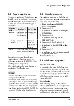
3.2 Type of application
The types of application 'Control valve'
and
'On/off valve'
are available. The manual
mode (MAN) and the automatic mode
(AUTO) can be selected with both types of
applications.
Operating
mode
Control valve
On/off valve
Automatic
The positioner uses
the set point w to
position the valve.
Discrete analysis of
the set point w
Reading
on display
Valve position x in
%
Valve position x in
% and O/C
(Open/Close) in
alternating
sequence
Manual
The positioner follows the manual set
point given over local operation.
Depending on the type of application,
certain diagnostic functions cannot be
performed or analyzed (
u
EB 8389-1S on
EXPERTplus valve diagnostics).
After initialization and a reset, the type of
application 'On/off valve' is set.
−
Section 7.8 contains details on discrete
analysis of on/off valves.
−
In manual mode, an on/off valve can be
moved past 100 % of the nominal range
(with the closed position for AIR TO OPEN)
or below 0 % of the nominal range (with
the closed position for AIR TO CLOSE). See
section 7.1 for the valve closed position.
3.3 Mounting versions
The positioner is suitable for the following
types of attachment using the corresponding
accessories (see section 3.8):
−
Direct attachment to SAMSON
Type 3277 Actuator
Î
See section 5.3.
−
Attachment to actuators according to
IEC 60534-6:
Î
See section 5.4.
−
Attachment according to VDI/
VDE 3847-1/-2:
Î
See section 5.5 and section 5.6.
−
Attachment to Type 3510 Micro-flow
Valve
Î
See section 5.7.
−
Attachment to rotary actuators accord-
ing to VDI/VDE 3845:
Î
See section 5.8.
3.4 Additional equipment
Inductive limit switch
In this version, the rotary shaft of the posi-
tioner carries an adjustable tag which actu-
ates the built-in proximity switch. The option-
al inductive contact (11) is connected to A1,
while the remaining software limit switch is
connected to A2.
Solenoid valve
If the operating voltage for the solenoid
valve (12) falls below 12 V, the supply pres
-
sure for the booster is vented to the atmo-
sphere. As a result, the actuator is vented
and the control valve moves to the fail-safe
Note
Summary of Contents for TROVIS SAFE 3730-6
Page 12: ...12 EB 8384 6S EN...
Page 16: ...16 EB 8384 6S EN...
Page 22: ...22 EB 8384 6S EN...
Page 40: ...40 EB 8384 6S EN...
Page 42: ...42 EB 8384 6S EN...
Page 82: ...82 EB 8384 6S EN...
Page 90: ...90 EB 8384 6S EN...
Page 96: ...96 EB 8384 6S EN...
Page 132: ...132 EB 8384 6S EN...
Page 152: ...152 EB 8384 6S EN...
Page 155: ...EB 8384 6S EN 155...
Page 156: ...156 EB 8384 6S EN...
Page 157: ...EB 8384 6S EN 157...
Page 158: ...158 EB 8384 6S EN...
Page 159: ...EB 8384 6S EN 159...
Page 160: ...160 EB 8384 6S EN...
Page 161: ...EB 8384 6S EN 161...
Page 162: ...162 EB 8384 6S EN...
Page 163: ...EB 8384 6S EN 163...
Page 164: ...164 EB 8384 6S EN...
Page 165: ...EB 8384 6S EN 165...
Page 166: ...166 EB 8384 6S EN...
Page 167: ...EB 8384 6S EN 167...
Page 182: ...182 EB 8384 6S EN...
Page 183: ...EB 8384 6S EN 183...

