88
EB 8384-6S EN
5.16.2
Switching amplifier
according to EN 60947-
5-6
For operation of the limit switches, switching
amplifiers must be connected in the output
circuit. To ensure the operating reliability of
the positioner, the amplifiers should comply
with the limit values of the output circuits
conforming to EN 60947-5-6.
Observe the relevant regulations for installa-
tion in hazardous areas.
5.16.3 Establishing communica-
tion
Communication between computer and posi-
tioner using an FSK modem or handheld
communicator (if necessary, using an isola-
tion amplifier) is based on the HART
®
proto-
col.
Viator FSK modem
−
RS-232
Not ex
Order no. 8812-0130
−
PCMCIA Not ex
Order no. 8812-0131
−
USB
Not ex
Order no. 8812-0132
If the load impedance of the controller or
control station is too low, an isolation ampli-
fier must be connected between controller
and positioner (interfacing as for positioner
connected in hazardous areas). See Fig. 34.
If the positioner is used in hazardous areas,
an explosion-protected isolation amplifier
must to be used.
Using the HART
®
protocol, all connected
control room and field units can be ad
-
dressed individually using a point-to-point
connection or the standard (multidrop) bus.
Point-to-point:
The bus address/polling address must al
-
ways be set to zero (0).
Standard bus (multidrop):
In the standard bus (multidrop) mode, the
positioner follows the analog current signal
(set point) in the same way as for point-to-
point communication. This operating mode
is, for example suitable for split-range oper-
ation of positioners (series connection).
The bus address/polling address has to be
within a range of 1 to 15.
Communication errors may occur when the
process controller/control station output is
not HART
®
-compatible.
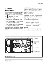
Alternatively, a 250 Ω resistor can be con-
nected in series and a 22 µF capacitor can
be connected in parallel to the analog out
-
put. The load for the controller output will in
-
crease as a result.
22 µF
250 Ω
Controller/
control station
Fig. 32:
Adapting the output signal
Note
Summary of Contents for TROVIS SAFE 3730-6
Page 12: ...12 EB 8384 6S EN...
Page 16: ...16 EB 8384 6S EN...
Page 22: ...22 EB 8384 6S EN...
Page 40: ...40 EB 8384 6S EN...
Page 42: ...42 EB 8384 6S EN...
Page 82: ...82 EB 8384 6S EN...
Page 90: ...90 EB 8384 6S EN...
Page 96: ...96 EB 8384 6S EN...
Page 132: ...132 EB 8384 6S EN...
Page 152: ...152 EB 8384 6S EN...
Page 155: ...EB 8384 6S EN 155...
Page 156: ...156 EB 8384 6S EN...
Page 157: ...EB 8384 6S EN 157...
Page 158: ...158 EB 8384 6S EN...
Page 159: ...EB 8384 6S EN 159...
Page 160: ...160 EB 8384 6S EN...
Page 161: ...EB 8384 6S EN 161...
Page 162: ...162 EB 8384 6S EN...
Page 163: ...EB 8384 6S EN 163...
Page 164: ...164 EB 8384 6S EN...
Page 165: ...EB 8384 6S EN 165...
Page 166: ...166 EB 8384 6S EN...
Page 167: ...EB 8384 6S EN 167...
Page 182: ...182 EB 8384 6S EN...
Page 183: ...EB 8384 6S EN 183...

