72
EB 8384-6S EN
Mounting and start-up
Pressure gauge attachment
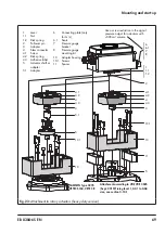
The mounting sequence shown in Fig. 24 re-
mains unchanged. Screw a pressure gauge
bracket onto the connections
A
1
and
Z
.
Pressure gauge
bracket
G ¼
1400-7106
¼ NPT
1400-7107
Pressure gauges for supply air Z and output
A1 as listed in Table 3 to Table 8.
5.10 Attachment of external
position sensor
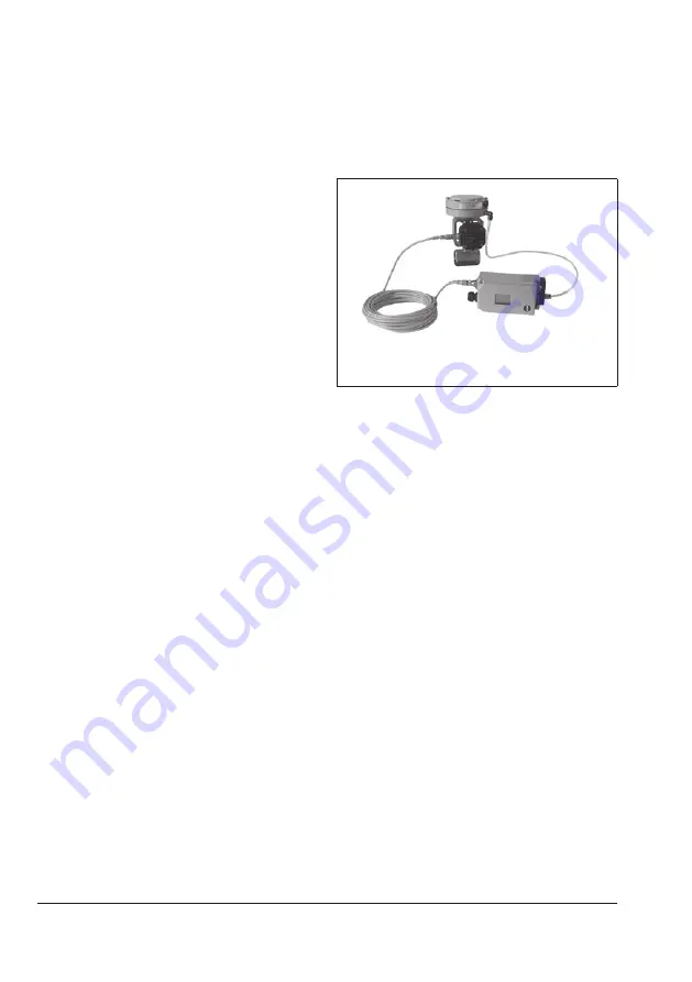
Positioner unit with sensor mounted on a mi-
cro-flow valve
Î
Required mounting parts and accesso
-
ries: Table 8
In the positioner version with an external po-
sition sensor, the sensor located in a separate
housing is attached over a plate or bracket to
the control valve. The travel pick-off corre-
sponds to that of a standard device.
The positioner can be mounted as required to
a wall or a pipe.
For the pneumatic connection
either a con-
necting plate (6) or a pressure gauge bracket
(7) must be fixed to the housing, depending
on the accessory chosen. Make sure the seals
(6.1) are correctly inserted (see Fig. 8, bot-
tom right).
For the electrical connection
a 10 meter con
-
necting lead with M12x1 connectors is in-
cluded in the scope of delivery.
Summary of Contents for TROVIS SAFE 3730-6
Page 12: ...12 EB 8384 6S EN...
Page 16: ...16 EB 8384 6S EN...
Page 22: ...22 EB 8384 6S EN...
Page 40: ...40 EB 8384 6S EN...
Page 42: ...42 EB 8384 6S EN...
Page 82: ...82 EB 8384 6S EN...
Page 90: ...90 EB 8384 6S EN...
Page 96: ...96 EB 8384 6S EN...
Page 132: ...132 EB 8384 6S EN...
Page 152: ...152 EB 8384 6S EN...
Page 155: ...EB 8384 6S EN 155...
Page 156: ...156 EB 8384 6S EN...
Page 157: ...EB 8384 6S EN 157...
Page 158: ...158 EB 8384 6S EN...
Page 159: ...EB 8384 6S EN 159...
Page 160: ...160 EB 8384 6S EN...
Page 161: ...EB 8384 6S EN 161...
Page 162: ...162 EB 8384 6S EN...
Page 163: ...EB 8384 6S EN 163...
Page 164: ...164 EB 8384 6S EN...
Page 165: ...EB 8384 6S EN 165...
Page 166: ...166 EB 8384 6S EN...
Page 167: ...EB 8384 6S EN 167...
Page 182: ...182 EB 8384 6S EN...
Page 183: ...EB 8384 6S EN 183...

