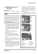
EB 8384-6S EN
85
If there are no specifications, calculate as
follows:
Î
Required supply pressure = Upper bench
range value + 1 bar
5.15.4 Signal pressure (output)
The signal pressure at the output (38) of the
positioner can be restricted to 1.4 bar,
2.4 bar or 3.7 bar in Code 16.
The limitation is not activated [7.0 bar] by
default.
5.16 Electrical connections
For electrical installation, observe the rele-
vant electrotechnical regulations and the ac-
cident prevention regulations that apply in
the country of use. In Germany, these are
the VDE regulations and the accident pre
-
vention regulations of the employers’ liability
insurance.
Risk of fatal injury due to the formation of
an explosive atmosphere.
The following regulations apply to installation
in hazardous areas: EN 60079-14
(VDE 0165, Part 1) Explosive Atmospheres –
Electrical Installations Design, Selection and
Erection.
Incorrect electrical connection will render the
explosion protection unsafe.
−
Adhere to the terminal assignment.
−
Do not undo the enameled screws in or on
the housing.
−
Do not exceed the maximum permissible
values specified in the EC type examina-
tion certificates when interconnecting in-
trinsically safe electrical equipment (U
i
or
U
0
, l
i
or I
0
, P
i
or P
0
, C
i
or C
0
and L
i
or L
0
).
The ambient temperature ranges of the ta-
bles in the EC type examination certificate
apply for the assignment between the per-
missible ambient temperature, temperature
class, maximum short-circuit currents and
maximum power P
i
and P
0
.
The following applies additionally:
For posi-
tioners in type of protection Ex tb
(TROVIS SAFE 3730-65) and type of protec
-
tion Ex nA (TROVIS SAFE 3730-68), the ca
-
ble glands and blanking plugs must be certi-
fied according to EN 60079-7 (Ex e).
Selecting cables and wires
Observe
Clause 12 of EN 60079-14
for in-
stallation of the intrinsically safe circuits.
Clause 12.2.2.7 applies when running multi-
core cables or wires with more than one in-
trinsically safe circuit.
The radial thickness of the insulation of a
conductor for common insulating materials
(e.g. polyethylene) must not be smaller than
0.2 mm.
The diameter of an individual wire
in a fine-stranded conductor must not be
smaller than 0.1 mm. Protect the conductor
ends against splicing, e.g. by using wire-end
ferrules.
When two separate cables or wires are used
for connection, an additional cable gland
can be installed. Seal cable entries left un-
used with plugs. Fit equipment used in ambi-
DANGER
!
WARNING
!
Summary of Contents for TROVIS SAFE 3730-6
Page 12: ...12 EB 8384 6S EN...
Page 16: ...16 EB 8384 6S EN...
Page 22: ...22 EB 8384 6S EN...
Page 40: ...40 EB 8384 6S EN...
Page 42: ...42 EB 8384 6S EN...
Page 82: ...82 EB 8384 6S EN...
Page 90: ...90 EB 8384 6S EN...
Page 96: ...96 EB 8384 6S EN...
Page 132: ...132 EB 8384 6S EN...
Page 152: ...152 EB 8384 6S EN...
Page 155: ...EB 8384 6S EN 155...
Page 156: ...156 EB 8384 6S EN...
Page 157: ...EB 8384 6S EN 157...
Page 158: ...158 EB 8384 6S EN...
Page 159: ...EB 8384 6S EN 159...
Page 160: ...160 EB 8384 6S EN...
Page 161: ...EB 8384 6S EN 161...
Page 162: ...162 EB 8384 6S EN...
Page 163: ...EB 8384 6S EN 163...
Page 164: ...164 EB 8384 6S EN...
Page 165: ...EB 8384 6S EN 165...
Page 166: ...166 EB 8384 6S EN...
Page 167: ...EB 8384 6S EN 167...
Page 182: ...182 EB 8384 6S EN...
Page 183: ...EB 8384 6S EN 183...

