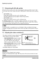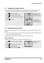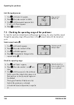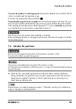
EB 8384-6S EN
97
EB 8384-6S
97
Operating the positioner
7 Operating the positioner
Risk of malfunction due to incorrect sequence of mounting, installation and start-up.
Observe the following sequence.
1. Remove the protective caps from the pneumatic connections.
2. Mount the positioner on the valve.
3. Connect the supply air.
4. Connect the electrical power.
5. Perform settings.
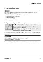
Reading after connecting the electrical power supply:
The wrench icon blinks on the display when the
positioner has not
yet been initialized
. The reading indicates the lever position in
degrees in relation to the mid-axis.
Code 0 is displayed when a
positioner has been initialized
. The
positioner is in the last active operating mode.
The positioner performs a test in the start-up phase while following its automation task at the
same time.
Risk of injury due to the actuator stem extending or retracting.
Do not touch or block the actuator stem.
During the start-up phase, operation on site is unrestricted, yet write access is limited.
NOTICE
!
WARNING
!
Summary of Contents for TROVIS SAFE 3730-6
Page 12: ...12 EB 8384 6S EN...
Page 16: ...16 EB 8384 6S EN...
Page 22: ...22 EB 8384 6S EN...
Page 40: ...40 EB 8384 6S EN...
Page 42: ...42 EB 8384 6S EN...
Page 82: ...82 EB 8384 6S EN...
Page 90: ...90 EB 8384 6S EN...
Page 96: ...96 EB 8384 6S EN...
Page 132: ...132 EB 8384 6S EN...
Page 152: ...152 EB 8384 6S EN...
Page 155: ...EB 8384 6S EN 155...
Page 156: ...156 EB 8384 6S EN...
Page 157: ...EB 8384 6S EN 157...
Page 158: ...158 EB 8384 6S EN...
Page 159: ...EB 8384 6S EN 159...
Page 160: ...160 EB 8384 6S EN...
Page 161: ...EB 8384 6S EN 161...
Page 162: ...162 EB 8384 6S EN...
Page 163: ...EB 8384 6S EN 163...
Page 164: ...164 EB 8384 6S EN...
Page 165: ...EB 8384 6S EN 165...
Page 166: ...166 EB 8384 6S EN...
Page 167: ...EB 8384 6S EN 167...
Page 182: ...182 EB 8384 6S EN...
Page 183: ...EB 8384 6S EN 183...

