3.2.2 Adjustment with Type 5824
Actuator
1. Retract the actuator stem by turning the
handwheel counterclockwise or by
applying a corresponding control signal
from the control device.
2. Continue as described in section 3.2.1.
3.2.3 Adjustment with Type 5825
Actuator
1. Switch the control device to manual mode
and change the control signal to retract
the actuator stem all the way and com-
press the spring mechanism.
EB 3135-1 EN
7
Operation
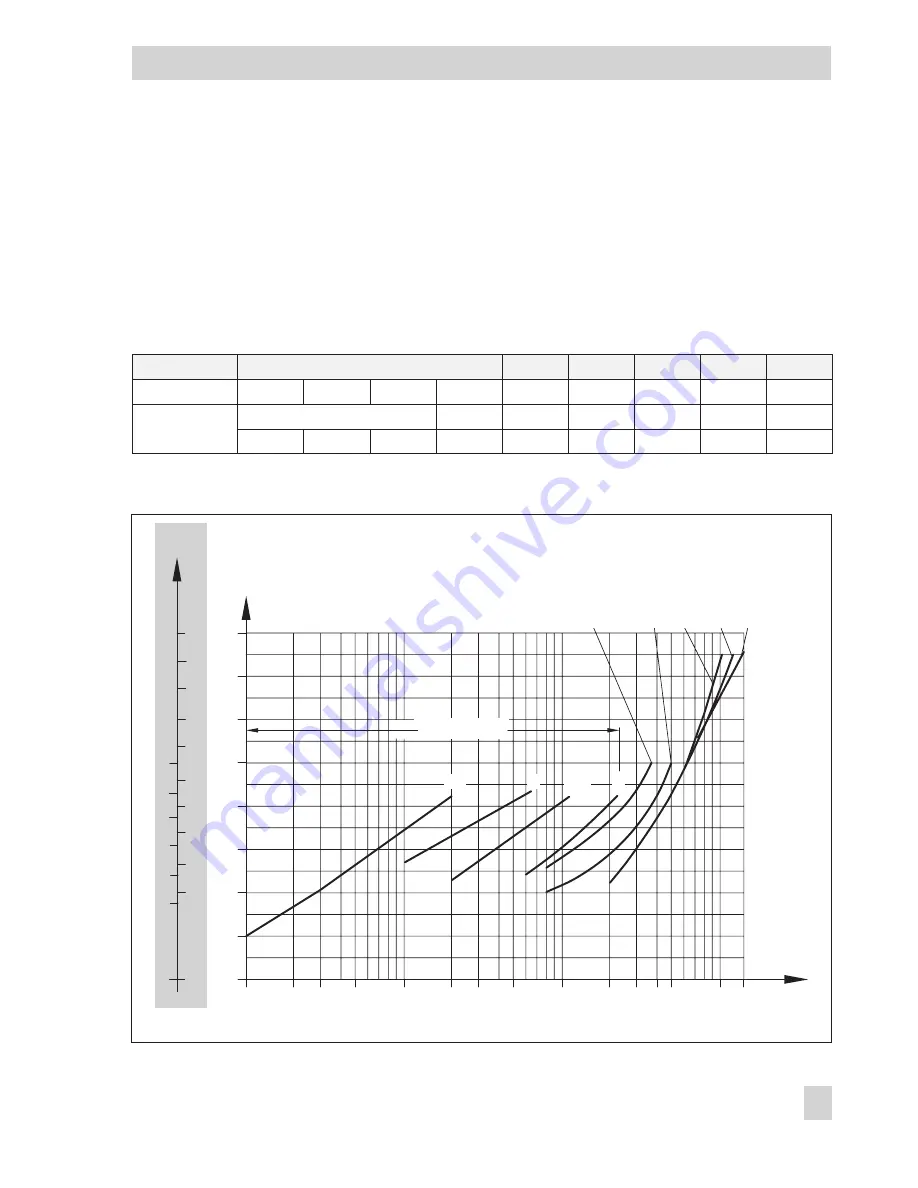
Fig. 3 · Diagram for adjusting the flow rate
0
3
4
5
5
6
10
12
0
9
4
3
2
DN 32 to 50
DN 15 to 25
6
7
11
0.01
0.05
0.1
0.5
1
5
10
1
0
2
3
4
5
6
7
8
DN 15, K
vs
...
32
40 50
V˚
m3/h
0.02 0.03
0.2 0.3
2
3 4
15
0.4
1
2.5
4
25
DN20
7
8
Turns of the set point screw
Nominal size
15
20
25
32
40
1)
50
1)
K
VS
0.4
1
2.5
4
6.3
8
12.5
16/20
2)
20/25
2)
Set point range
flow rate m³/h
0.6...1.3
3)
0.8...2.3
3)
0.8...3.5
3)
2...5.8
3)
3...9.1
3)
4...14.1
3)
0.03...0.2 0.1...0.64 0.2...1.2 0.6...2.5 0.8...3.6
0.8...5
2...10
3...12.5
4...15
1)
Also available as version with flanged body
2)
K
VS
for flanged body
3)
A higher noise level will occur if the specified set point values are exceeded


