background image

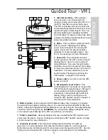
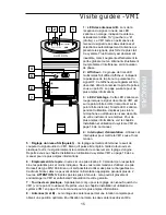
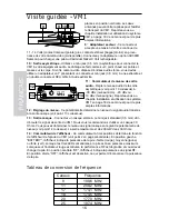
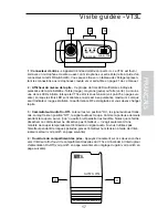
Introduction / System Features

Congratulations on purchasing the Samson VM1 micro diversity receiver—part of our
renowned VHF TD Series Wireless System!  Although this product is designed for easy
operation, we suggest you first take some time to go through these pages so you can fully
understand how we’ve implemented a number of unique features.

Every wireless system consists of at least two components—a transmitter and a receiver,
both of which must be tuned to the same channel (that is, the same radio frequency) in
order to operate correctly.*  The Samson VM1 system you have purchased operates in
the 173.8 - 213.2 MHz frequency range and contains a VM1 micro diversity receiver and
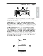
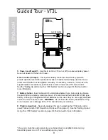
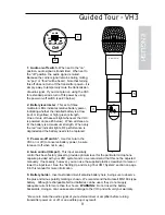
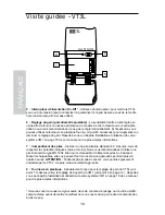
one of our VHF TD Series transmitters: either a VT3L belt-pack transmitter (for lavalier
microphone or headset applications) or a VH3 hand-held microphone transmitter
(available in a wide variety of popular capsules).

The VM1 system is specially designed to enable the production of professional audio
tracks to accompany your video shoot or live broadcast.  The use of a handheld mic
transmitter or lavalier microphone connected to a beltpack transmitter effectively isolates
the performer from unwanted ambient sounds such as video camera motor noise or room
sounds made by the camera operator or video crew.  Because the VM1 receiver is
extremely small and lightweight, it can be attached easily to any video camera using the
supplied strip of velcro, and can even be powered directly by the camera’s own 12-volt
power supply, if available.

In this manual, you’ll find a more detailed description of the features of the VM1 system, as
well as a guided tour through all components, step-by-step instructions for setting up your
system, wiring diagrams and tables, and full specifications.  If your VM1 system was
purchased in the United States, you’ll also find a warranty card enclosed—don’t forget to
fill it out and mail it!  This will enable you to receive online technical support and will allow
us to send you updated information about this and other Samson products in the future.
If your VM1 system was purchased outside of the U. S., contact your local distributor for
warranty details.

SPECIAL NOTE for U.S. purchasers: Should your VM1 system ever require servicing, a
Return Authorization number (RA) is necessary.  Without this number, the unit will not be
accepted.  If your VM1 system was purchased in the United States, please call Samson at
1-800-372-6766 for a Return Authorization number prior to shipping your unit.  If possible,
return the unit in its original carton and packing materials.  If your VM1 system was
purchased outside of the U. S., contact your local distributor for servicing information.

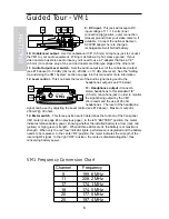
*  Your receiver and transmitter have been factory preset to utilize the same channel.
A listing of the six available channels and their corresponding VHF frequencies can be
found on page 4 of this manual.

System Features

Designed for use in both live sound and sound contracting applications, the Samson VM1
system provides a high performance, cost effective solution, utilizing state-of-the-art
technology in wireless communications.  Main features include:

• Six different available channels, all operating in the VHF bandwidth, and all designed for

simultaneous use.  This means that you can use multiple VM1 systems (each tuned to a
different channel) in the same location without interference.

3

ENGLISH

Summary of Contents for VHF Micro VHF Micro TRUE DIVERSITY WIRELESS

Page 1: ...O W N E R S M A N U A L Micro T R U E D I V E R S I T Y W I R E L E S S S Y S T E M...

Page 2: ...FRANCAIS Introduction Caract ristiques du Syst me 13 Visite guid e VM1 15 Tableau de conversion de fr quence 16 Visite guid e VT3L 17 Visite guid e VH3 19 Param trage et utilisation du syst me VM1 20...

Page 3: ...tures of the VM1 system as well as a guided tour through all components step by step instructions for setting up your system wiring diagrams and tables and full specifications If your VM1 system was p...

Page 4: ...hnology maximizes active range up to 300 feet and reduces potential interference problems through automatic switching between two independent antennas Built in companding noise reduction in all compon...

Page 5: ...quelch Level control This control determines the maximum range of the VM1 before audio signal dropout Although it can be adjusted using the supplied plastic screwdriver it should normally be left at i...

Page 6: ...3 Headphones output Connect a stereo headphone to this standard 1 8 3 5 mm mini phone jack in order to monitor the signal being output by the VM1 We recommend the use of 30 ohm headphones The level of...

Page 7: ...erformance is degraded and the battery needs to be replaced 3 Audio on off switch When set to the on position audio signal is transmitted When set to the off position the audio signal is muted Because...

Page 8: ...d 9 volt alkaline battery here being sure to observe the plus and minus polarity markings shown We recommend the Duracell MN 1604 type battery Although rechargeable Ni Cad batteries can be used they d...

Page 9: ...power be sure to leave it off when not in use 4 Gain control trimpot This input sensitivity control has been factory preset to provide optimum level for the particular microphone capsule provided wit...

Page 10: ...Open and swing the door open note that the door is hinged and is not intended to be removed from the receiver case Make sure the power switch is set to Off 3a If your system contains a VT3L belt pack...

Page 11: ...lustration on the right as close to your mouth as possible but off to one side to minimize nasality and unobstructed by clothing Bear in mind also that omni microphones mics which pick up signal from...

Page 12: ...e particular environment your system is used in you may need to reduce that range somewhat in order to eliminate band noise when the transmitter is turned off To do so use the provided screwdriver to...

Page 13: ...composants des instructions d taill es pour l installation de votre syst me des sch mas et des tableaux de c blage ainsi que toutes les caract ristiques techniques Si vous avez achet votre syst me VM...

Page 14: ...un choix automatique entre deux antennes ind pendants Un compresseur expanseur de r duction de bruit int gr dans tous les composants permet d obtenir un son d une puret exceptionnelle les sifflements...

Page 15: ...ion Utilisez cet interrupteur pour mettre le VM1 sous et hors tension 5 R glage du niveau SQ Squelch Ce r glage permet de d terminer le seuil de coupure du signal audio du VM1 Bien qu il puisse tre r...

Page 16: ...on du syst me VM1 en page 18 de ce manuel pour de plus amples informations 12 R glage du niveau Ce potentiom tre d termine le niveau du signal audio transmis la sortie casque voir point 13 ci dessous...

Page 17: ...e et vous devez changer la pile 3 Commutateur Audio On Off Lorsqu il est en position On le signal audio est trans mis Lorsqu il est en position Off le signal audio est coup Comme la porteuse demeure p...

Page 18: ...ne pile alcaline standard 9 V Assurez vous de respecter les polarit s indiqu es plus et moins Nous vous recommandons d utiliser une pile Duracell de type MN 1604 Bien qu il soit possible d utiliser de...

Page 19: ...hors tension lorsqu il n est pas utilis 4 R glage du gain potentiom tre ajustable Ce r glage de la sensibilit d entr e a t program m en usine afin de fournir un niveau maximum en fonction de la capsul...

Page 20: ...e du bo tier Assurez vous que l interrupteur d alimentation est d sactiv Off 3a Si votre syst me contient un metteur la ceinture VT3L rep rez l ouverture du compartiment de la pile et abaissez le levi...

Page 21: ...micros saisissant le signal dans toutes les directions g n rent plus de probl mes de Larsen que les microphones unidirectionnels cardio de ou hypercardio de En g n ral vous pouvez viter le Larsen en v...

Page 22: ...Q est au minimum le syst me VM1 permet toujours une port e maximale sans d crochage Cependant selon l environnement particulier dans lequel votre syst me est utilis vous aurez peut tre besoin de r dui...

Page 23: ...ise Anweisungen zum Aufstellung und Betrieb Ihres Systems Abbildungen der Verkabelungen und eine gro e Anzahl technischer Daten Wenn Sie Ihren VM1 in den USA erworben haben f llen Sie die beiliegende...

Page 24: ...glichen die restliche Leistung der Batterie zu berpr fen Die Technologie True Diversity vergr ert den aktiven Bereich bis zu 100 m und ver mindert Interferenzen dank des automatischen Auswahlverfahre...

Page 25: ...VM1 5 SQ Squelch Pegel Regler Dieser Regler bestimmt den maximalen Empfangsbereich des VM1 vor dem Abschneiden des Audiosignals Obwohl Sie diesen Regler mit Hilfe des beiliegenden Plastikschraubdreher...

Page 26: ...gel des Audiosignals ein welches ber die Kopfh rerausg nge ausgegeben wird 13 Kopfh rerausg nge Verbinden Sie einen Stereo Kopfh rer mit dieser 3 5 mm Mini Buchse um Wir empfehlen Ihnen 30 Ohm Kopfh r...

Page 27: ...LED leuchtet wird die RF Kapazit t verschlechtert und die Batterie mu ausgewechselt werden 3 Audio On Off Schalter Wenn dieser Schalter in der Stellung On steht wird das Audiosignal gesendet Steht der...

Page 28: ...en Sie hier eine normale 9 Volt Batterie ein wobei Sie beim Einlegen auf die Polarit ten plus und minus achten Wir empfehlen Ihnen die Batterieart Duracell MN 1604 Sie k nnen auch wiederaufladbare Bat...

Page 29: ...den VH3 ein oder auszuschalten zur Verl ngerung der Batterielebensdauer versichern Sie sich da der Schalter ausgeschaltet ist 4 Gain Regler Abgleichpotentiometer Dieser Regler bestimmt die Eingangsemp...

Page 30: ...ie auf der Vorderseite des VM1 befindlichen Einschnitte der Batterieabdeckung nach unten Open und schwingen Sie die Abdeckung auf um an das Batteriefach zu gelangen Beachten Sie da die Abdeckung mit S...

Page 31: ...R ckkopplungen sind als unidirektionale Kardioide oder Hyperkardioid Im Allgemeinen sollte der Betrieb von Mikrofonen unmittelbar vor eine Lautsprecheranlage vermieden werden falls dies nicht zu umgeh...

Page 32: ...en Allerdings kann es abh ngig von den tats chlichen Umgebungsgegenheiten notwendig sein diese Reichweite etwas zu verk rzen um bei abgeschaltetem Sender Bandrauschen oder andrere St rger usche zu bes...

Page 33: ...as de su nuevo sistema VM1 as como un recorrido guiado a trav s de todos los componentes instrucciones paso a paso sobre los ajustes y el funcionamiento de su sistema y todas las especificaciones t cn...

Page 34: ...pila que est instalada La tecnolog a de diversidad real lleva al m ximo el rango activo hasta 300 pies y reduce los problemas potenciales de interferencias por medio de un cambio autom tico entre dos...

Page 35: ...trol determina el rango m ximo del VM1 antes de la desaparici n de la se al audio Aunque se puede ajustar utilizando el destornillador de pl stico que se incluye deber a dejarlo normalmente en su ajus...

Page 36: ...es vea el punto 13 siguiente 13 Salida de auriculares Conecte unos auriculares stereo a esta toma de entrada mini jack de 1 8 3 5 mm de auriculares stereo para monitorizar la se al que est siendo emit...

Page 37: ...e que cambie la pila lo antes posible 3 Interruptor on off de audio Cuando se coloca en la posici n on se transmite la se al audio Cuando se coloca en la posici n off la se al audio queda anulada Dado...

Page 38: ...ila Coloque aqu una pila alcalina de 9 voltios standard ase gur ndose de seguir las indicaciones de colocaci n de los polos positivo y negativo Recomendamos las pilas del tipo Duracell MN 1604 Aunque...

Page 39: ...ga de la pila aseg rese de dejar este interruptor en off cuando no utilice la unidad 4 Control de ganancia ajuste giratorio Este control de sensibilidad de entrada ha sido prefijado de f brica para of...

Page 40: ...pa para poder acceder al compartimento de la pila Tenga en cuenta que esta tapa est fija con una especie de bisagra y que por tanto no se debe separar de la carcasa del receptor Aseg rese de que el in...

Page 41: ...hacia un lado para reducir al m nimo el efecto nasal y evitando que ninguna ropa interfiera Tenga en cuenta tambi n que los micr fonos omnidireccionales micros que captan la se al de todas las direcc...

Page 42: ...creto en el que utilice su sistema puede que tenga que reducir este rango algo para eliminar el ruido de banda que aparece cuando el trans misor est apagado Para hacerlo utilice el destornillador que...

Page 43: ...ED JUMP TO PIN 2 WHITE SONY ECM144 SHIELD WHITE JUMP TO PIN 2 SENNHEISER MKE2 SHIELD JUMP TO PIN 2 BLUE RED SENNHEISER MKE40 SHIELD JUMP TO PIN 2 BLUE RED SENNHEISER MKE48 SHIELD JUMP TO PIN 2 BLUE RE...

Page 44: ...ndicator Battery high medium low Dimensions VT3L 65 W x 22 H x 100 D mm 2 6 x 87 x 4 in VH3 37 W x 240 H mm 1 46 x 9 45 in Weight 110 grams 3 9 oz Receiver R cepteur Empf nger Receptor VM1 Local Oscil...

Page 45: ...d licensability depends on the user s classification application and frequency selected This device complies with RSS 210 of Industry Science Canada Operation is subject to the following two condition...

Reviews: