background image

12

Operating the XM410

BASIC OPERATION

The following section explains the basic operation of the XM410.

CONNECTING MICROPHONES AND INSTRUMENTS

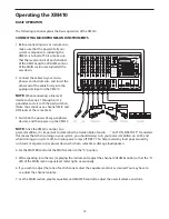
1.  Before connecting mics or instruments, 

make sure that the power of all your 

systems components, including the 

XM410, is turned off.  Also, make sure 

that the level controls of each channel 

of the XM410 and the VOLUME control 

of the MAIN section are turned all the 

way down.

2.  Connect the cables to your micro-

phones and instruments, and insert the 

other end of the cable firmly into the 

appropriate input on the XM410.

NOTE:


When connecting a line level 

device to channels 1 through 6, it’s a 

good idea to start with the pad switch on.  

(Note: You cannot use a channel’s MIC and 

LINE jacks at the same time.)

3.  Switch on the power of any peripheral 

devices, and then power up the XM410.

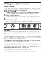
NOTE:

 Since the XM410 contains two 

power amplifiers, it is important to remember the Golden Rule of audio …  " LAST ON, FIRST OFF".  Translated, 

this means that when turning on your system, you should always turn your power amplifiers on LAST, and 

when turning your system off,  turn your power amps off FIRST.  This helps avoid any loud pops caused by 

rush current at power up or power down, which can sometimes damage loudspeakers .

4. Set the MASTER control of the MAIN section to the "5" position.

5.  While speaking into the mic (or playing the instrument), adjust the channel VOLUME control so that the "0" 

LED of the MAIN section peak level meter lights occasionally.

6. If you wish to adjust the tone of each channel, adjust the equalizer controls as desired. You may have to 

  re-adjust the channel volume.

7. Use the MAIN section graphic equalizer and MASTER control to adjust the overall volume and tone.

Summary of Contents for XM 410

Page 1: ...Powered Mixers SIX CHANNEL POWERED MIXER WITH 24BIT DIGITAL EFFECTS...

Page 2: ...powered mixer as well a descrip tion of its front and rear panels step by step instructions for its setup and use and full specifications You ll also find a warranty card enclosed please don t forget...

Page 3: ...denser microphones connect easily to the low noise mic pre amps with available 48 Volt Phantom Power The 3 Band EQ on each channel enables you to tailor the tonal response for each input Two Auxiliary...

Page 4: ...Controls and Functions FRONT PANEL LAYOUT...

Page 5: ...POWER AMP 1 A B jacks if the POWER AMP select switch is set to MAIN MONITOR AUX 2 EFX Effects Send The XM410 provides high quality 24 Bit digital effects and the level of effects can be set independen...

Page 6: ...nternal DSP EFX ON switch The EFX ON control is used to turn the internal Digital Effect on and off The effects are bypassed when the switch is in the out position and the display shows two dashes 6 7...

Page 7: ...UTION Only change the power amp mode switch when the XM410 s power is SWITCHED OFF MAIN MONITOR With this setting the MAIN and MONITOR sections can be used independently The MAIN bus signal will be se...

Page 8: ...that frequency by up to 12dB Once you set a response curve using the Graphic Equalizer the EQ curve is applied to both the MAIN bus signal that is output to the speakers and the line level signal whic...

Page 9: ...ITOR OUT jack MONITOR Level Meter The OUTPUT LEVEL METER allows you to monitor the level of the signal which is being sent to the MONITOR OUT jack and MONITOR POWER AMPLIFIER NOTE To avoid distortion...

Page 10: ...e Input Use these inputs to connect Low Impedance microphones and low level signals from direct boxes The MIC inputs have a nominal operating level of 50dBV through 20dBV The MIC inputs also feature 4...

Page 11: ...jack and two more 8 ohm speakers can be daisy chained together and connected to the AMP 2 jack for a total of four speakers See the diagram on page 11 The total impedance load for each amplifier must...

Page 12: ...connected to the BRIDGE jack bridge connection For each of these the required speaker impedance will differ Refer to the following diagram and make sure that the speaker impedance is not less than th...

Page 13: ...h on the power of any peripheral devices and then power up the XM410 NOTE Since the XM410 contains two power amplifiers it is important to remember the Golden Rule of audio LAST ON FIRST OFF Translate...

Page 14: ...the EFX RTN knob in the MAIN MONITOR section to adjust the EFFECTS Return level The EFX control is the overall level control for the DSP effects processor If you are not using the XM410 in MAIN MONIT...

Page 15: ...for playing back a CD Tape or Mini Disk Below is a description of how you can play back a CD Tape or MD using the XM410 s TAPE INPUT 1 Turn the TAPE IN level control and the VOLUME level control all...

Page 16: ...47 RIGHT LEFT RIGHT LEFT GROUND OUTPUT 250W 47 SERVO 550 STUDIO AMPLIFIER RIGHT LEFT BRIDGED MONO STEREO INPUTS BALANCED 10K7 0dBm0 TIP RING SLEEVE TIP RING SLEEVE GND This system shows the XM410 pow...

Page 17: ...oni tor speakers speaker connected to POWER AMP 1 For inputs two microphones are con nected to channel 1 and 2 s low impedance inputs and the output of the Bass Direct Box is also connected to the Low...

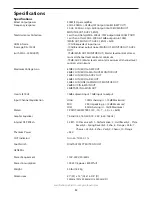
Page 18: ...MIC to MAIN OUT MONITOR OUT 54dB CH IN MIC to AUX 2 OUT 30dB CH IN MIC to REC OUT 32dB CH IN LINE to MAIN OUT MONITOR OUT 26dB AUX IN to MAIN OUT 24dB TAPE IN to MAIN OUT Crosstalk 1KHz 70dB adjacent...

Page 19: ...87 Block Diagram Synoptique Blockdiagramm Diagrama de bloques Diagramma a Blocchi...

Reviews: